- Fly system
-
 Fly loft of the Theater Bielefeld in Germany
A fly system, flying system or theatrical rigging system, is a system of lines (e.g. ropes), blocks (pulleys), counterweights and related devices within a theatre that enable a stage crew to quickly, quietly and safely fly (hoist) components such as curtains, lights, scenery, stage effects and, sometimes, people (e.g. Peter Pan). Systems are typically designed to fly components between clear view of the audience and out of view, into the large opening, fly loft, above the stage.
Fly systems are often used in conjunction with other theatre systems, such as scenery wagons, stage lifts and stage turntables, to physically manipulate the mise-en-scène. [1]
Theatrical rigging is most prevalent in proscenium theatres with stage houses designed specifically to handle the significant dead and live loads associated with fly systems. Building, occupational safety, and fire codes limit the types and quantity of rigging permitted in a theatre based on stage configuration. Theatrical rigging standards are developed and maintained by organizations such as USITT and ESTA (now PLASA).
Contents
The line set
The line set is the fundamental machine of a typical fly system.
The function of a typical line set is to fly (raise and lower) a slender beam (typically a steel pipe) known as a batten by hoisting it with lift lines (typically synthetic rope or steel cable). By hanging scenery, lighting, or other equipment to a batten, they in turn may also be flown. A batten is said to be "flying in" when it is being lowered toward the stage, and "flying out" when it is being raised into the fly space. Battens may be just a few feet in length or may extend from one wing (side) of the stage to the other. A batten is suspended from above by at least two lift lines, but long battens may require six or more lift lines.
In manual rigging, a line set’s lift lines support weights opposite their connections to the batten in order to balance the gravity load of the batten and whatever it carries. The lift lines are reeved through a series of pulleys, known as blocks, that are mounted above the stage to fly loft structure. An operating line (a.k.a. hand line or purchase line) allows riggers on the fly crew to raise and lower the batten.
Automated rigging sometimes uses weights to help balance line set loads in a manner similar to manual counterweight rigging. Otherwise it relies solely on the motor power of an electric hoist to fly a line set.
Together, a series of parallel line sets regularly spaced up and down stage, commonly at 6", 8" or 9" centers, comprise the bulk of most fly systems. Theatrical rigging systems are made up of hemp, counterweight and/or automated line sets able to serve various functions.
Line set functions
Line sets are typically general purpose in function, meaning they can perform any number of functions which vary depending upon the requirements of a particular theatre production. For example, a general purpose line set can usually be quickly transformed into a drapery or scenery line set, but converting a general purpose line set into an electrical line set is more involved.
When a line set has a predetermined, relatively permanent, function it is known as a dedicated line set. Line set functions include:
- Drapery and track line set
Line sets often suspend theater drapes and stage curtains such as travelers, teasers (a.k.a borders), legs, cycs, scrims and tabs, as well as associated tracks, in order to mask and frame the stage and provide backdrops. Line sets are sometimes dedicated to particular draperies, such as the main (grand) curtain and main border (valance) that mask the proscenium opening, but drapery locations can often vary.
- Scenery line set
In many stage productions, theatrical scenery is mounted to line sets in order to be flown in and out so as to quickly change set pieces during the course of a performance. For example, painted soft and hard flats (e.g. muslin drops) and are commonly used to depict settings. Also, three-dimensional sets (e.g. box sets) may be flown.
 Electric line set flown in
- Electrical line set
Electrical line sets, commonly called electrics, are used to suspend and control lighting instruments and, in many cases, microphones and special effects equipment as well. Electrics may be temporarily "wired" with drop boxes (electrical boxes with outlets) or multicable fanouts dropped from the grid or draped from a fly gallery, or permanently wired with connector strips (specialized electrical raceways). [2]
There are normally at least three electrical line sets provided above the stage, with one just upstage of the proscenium wall, one mid-stage, and one just downstage of the cyclorama. Additional electrics are typically desirable.
Permanently wired electrical line sets are known as dedicated electrics, fixed electrics or house electrics. In addition to providing dimmed and switched outlets for lighting fixtures, connector strips may provide low-voltage controls (e.g. via DMX512 and Ethernet taps), for moving lights and effects, as well as microphone jacks. Power is fed to fixed electrics from terminal boxes at the grid deck via multicable. Single and double-purchase cable cradles mounted to lift lines can be used to drape the multicable, prolonging its lifespan and reducing the likelihood of conflict with adjacent line sets or lighting instruments. Pantographs are also used to drape the multicable feeding dedicated electric line sets.
Dedicated electrics typically employ truss battens (pipe over pipe) to facilitate cable snaking and to maximize lighting positions. In large professional theatres, such as the Philadelphia Academy of Music, an electric may take the form of a flying bridge (catwalk) that provides a walkable platform for electrician access to fixtures and effects. Flying bridges may also be used for followspot positions.
 Shell cloud line sets flown out
- Orchestra enclosure line set
It is not uncommon for the ceiling panels, clouds, of an orchestra shell to be flown. Larger, multi-use theaters that must frequently convert the stage from a drama theatre to a concert hall often make use of the fly system in this way. Before being flown the cloud is pivoted to a vertical orientation to minimize the space it requires for storage in the fly loft.
- Focus chair line set
A less common use for the fly system is the use of a focus chair system. This is a system where a small chair with fall protection equipment is suspended from a track that runs the length of a batten to which it is mounted. An electrician sits on the chair, and is flown out to the height of the electrics, to focus lighting instruments.
- Flying rig
Flying rigs are used to fly scenery or performers in a more elaborate fashion than typical line sets. A flying rig typically allows horizontal as well as vertical movement by paying out individual lift lines to varying lengths and/or through the use of tracks. Flying rigs usually involve specialized equipment and techniques operated by a relatively experienced crew. Peter Foy is known for his innovations in manual flying rigs, especially those used in theatrical productions of Peter Pan. Automated flying rigs, which synchronize multiple point hoists, are becoming more common as motor control systems become safer and more sophisticated.
- Fire Safety curtain
A permanently installed fire curtain line set, though not used for productions, is a typical element of a theatrical rigging system installation. Building and fire codes typically require that either a fire curtain or water deluge system be installed to separate an audience from the stage in the event of a fire.
Fly system types
Fly systems are broadly categorized as manual or automated (motorized). Manual fly systems are more specifically categorized as "hemp" (a.k.a. rope line) or "counterweight" systems.
"Hemp houses" (a reference to the manila hemp once most commonly used to make the ropes) exclusively use the centuries-old tradition of ropes, pulleys and sandbags to fly theatrical scenery in and out. Hemp rigging incorporates many nautical rigging techniques and equipment (e.g. block and tackle), and stems directly from that tradition. Counterweight rigging evolved from hemp rigging and generally handles scenery in a more controlled fashion.
Counterweight rigging replaces the hemp rope and sandbags of rope line (hemp) rigging with wire rope (steel cable) and metal counterweights, respectively. Those substitutions permit the flying of greater loads with a high degree of control, but with a loss of flexibility inherent to most hemp systems. Flexibility is lost because most components of a hemp system may be repositioned, while counterweight system components are relatively fixed. Old "hemp houses" lacked counterweight rigging, but today most manual rigging houses use a combination of counterweight rigging and, at least some, hemp rigging. For example, theaters that incorporate built-in, grid-based counterweight fly systems often will also support additional, spot hemp system line sets for spot-rigging (to spot something, in theatre jargon, simply means to (re)position something).
Manual rigging is also possible with hand (and drill-operable) hoists (winches), but relatively limited operating speeds preclude their use for most running applications.
Automated systems are becoming more prominent. They have the potential advantages of relatively high precision, speed and ease of control, but tend to be significantly more expensive than manual systems. Hoists of various types (e.g. line shaft, chain motor, etc.) are used. A conventional counterweight system may be automated by the incorporation of a motor and controls, in what is commonly called a motor-assist system. By using counterweight in such a manner, motor sizes can be kept relatively small.
The use of a particular type of fly system in a theater usually does not preclude the use of other rigging methods in the same theater.
Hemp rigging system
 A small pin-rail at stage level.
A hemp fly system, so named for the manila hemp rope that was once common in theatrical rigging, is both the oldest and simplest type of fly system.[3] Hemp systems are also known as rope line systems, or simply as rope systems.
Stage rigging techniques draw largely from ship rigging. That origin is most obvious with hemp rigging, which uses closely related technology and terminology. To this day, the stage is referred to as a deck in the manner of a ship's deck. Other expressions and technology that overlap the nautical and theatrical rigging worlds include: batten, belay, block, bo'sun, cleat, clew, crew, hitch, lanyard, pinrail, purchase, trapeze, and trim.
In a typical hemp system line set, the lift lines and hand (operating) lines are one and the same. The lift lines run from the batten up to loft blocks, across stage to a head block, and back down to a pin rail, where the lines are tied off, belayed, with belaying pins. A trim clamp (a.k.a. knuckle-buster) is used to attach sandbags to the lift lines to balance the load placed on the batten. The sandbags are usually filled to weigh a few pounds less than the load, making the line set batten-heavy (load-heavy) so it will fly in under its own weight when the lift lines are let out.
Another hand line, known as a jack line, may be used to lift the sandbags if they are heavier than the batten load. The jack line, which runs up to a loft block and back down to the trim clamp, is tied off to a belaying pin adjacent to the one used for the line sets lift lines, either at the same, or a secondary, pin rail.
Pulling on the hand lines of a hemp set flies a line set out. Pulling on the jack line flies a line set in.
Hemp systems can be easily configured for spot rigging, where lift lines must be frequently relocated. They are much less expensive and easier to install than counterweight fly systems, though somewhat more difficult to operate.
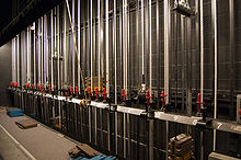
Counterweight rigging system
 Graphic depiction of a single lineset and the parts of a counterweight system. (A) Hoisting cables, (B) Turnbuckles, (C) Purchase line, (D) Arbor rod, (E) Spreader plates, (F) Cut steel counterweight, (G) Rope stop/lock (brake)/Lock rail, (H) Locking safety ring, (I) Tension sheave (block). Not shown: head sheave, loft sheaves, and batten.
 Locking rail and arbors
Developed in the first half of the 20th century, counterweight rigging systems are the most common fly systems in performing arts facilities today.
In a typical counterweight fly system, an arbor (carriage) is employed to balance the weight of the batten and attached loads to be flown above the stage. The arbor, which carries a variable number of metal counterweights, moves up and down vertical tracks alongside an offstage wall. In some lower-capacity fly systems, cable guide wires are used instead of tracks to guide the arbors and limit their horizontal play during vertical travel (movement).
The top of the arbor is permanently suspended by several wire rope lift lines, made of galvanized steel aircraft cable (GAC). The lift lines run from the top of the arbor up to the top of the fly tower, around the head block, across the stage to evenly spaced loft blocks, then down, terminating at the batten, a load-bearing pipe that spans much of the width of the stage.
If the loft blocks are mounted to the grid deck, at the loft block wells, the system is called a grid-mount, or upright counterweight rigging system. If the loft blocks are mounted to roof beams (loft block beams), the system is called an under-hung counterweight rigging system. Under-hung systems have the advantages of maintaining a clear grid deck surface for spot rigging and facilitating crew movement across the grid.
The arbor's vertical position is controlled by means of a rope known as the operating line, hand line, or purchase line. The operating line forms a loop by running from the bottom of the arbor down to and around the tension block, through the rope lock, up and over the head block and back down (alongside the lift lines), where it terminates at the top of the arbor. The head and tension blocks are located above and below the full extent of the arbor's travel (movement), respectively, thereby enabling an operator to pull the operating line up or down to move the arbor. When the arbor is raised via the operating line, the lift lines slacken, which causes the batten to lower under its own weight (and the weight of its load, if any). Conversely, when the arbor is lowered, the lift lines increase in tension, which in turn causes the batten to rise.
The combined weight of the arbor and its counterweights initially matches that of the batten so that when the batten is not being raised or lowered, it will tend to remain motionless at any arbitrary elevation above the stage. As more weight is added to the batten (in the form of curtains, scenery, lighting equipment, and rigging hardware), the system is rebalanced by adding more counterweights to the arbor. When the system is properly balanced, an unassisted operator (flyman) can lift the batten and its arbitrarily heavy load from the stage ("fly it out", in theatrical jargon), completely above the proscenium and out of view of the house, sometimes to heights in excess of 70 feet (21 m).
Some large theatres, such as the Metropolitan Opera House (Lincoln Center), have more than 100 independent, parallel counterweight line sets, while smaller venues may only have a few line sets for the most frequently adjusted loads, such as electrics.
Double-purchase counterweight system
Double purchase counterweight systems are sometimes used where the vertical travel of the counterweight arbor would be inadequate due to limited fly space or stage-level wing space. In systems of this type, the operating and lift lines are double-purchased so that the batten will travel twice the distance of the arbor. In other words, for every foot of arbor travel, the batten travels two feet. This often results in the arbors remaining well above the stage deck, leaving the otherwise occupied wing space usable for cast and crew.[4]
In a conventional counterweight system the operating and lift lines terminate at the top of the arbor after passing over the head block. In a double-purchase system, however, after passing over the head block the operating and lift lines pass through another block, which is mounted to the top of the arbor, before rising back up and terminating below the head block. In addition, the opposite end of a double-purchase operating line terminates at the fly gallery, off-stage wall, or stage deck, instead of the underside of the arbor, after passing through a block mounted at the underside of the arbor.[4] The additional blocks result in the arbor moving at half the rate of the lift and operating lines.
In order to compensate for the reduced arbor travel, the loaded arbors must weigh twice as much as the batten load, resulting in arbors that are twice as tall. The additional mass on the arbor increases inertia, and the additional blocks increase friction, resulting in linesets that are more difficult to operate. In addition, double-purchase linesets are more expensive to install and maintain. For those reasons, double-purchase line sets are generally avoided, or limited to a few sets within a counterweight system, unless space issues preclude the use of a single-purchase system. The use of an arbor pit is an alternative approach to dealing with limited space for arbor travel.
Automated rigging system
 A fly system winch mounted to the floor behind the locking rail. This winch, which operates a high capacity electric lineset, has a quad-wide arbor and is rated for 1,200-pound (540 kg) loads.
Electrical hoists (also referred to as winches) can facilitate coordination with cues, move extremely heavy line-sets, and significantly limit the required population of the fly crew. Despite those potential benefits, most hoists can fly line sets at only a fraction of the speed that an experienced flyman can achieve manually.
There are two general categories of motorized fly systems, motor-assist and dead-haul.
Motor-assist systems very closely resemble standard counterweight fly systems described above, however a drum winch, typically mounted behind the locking rail below the arbor, is used to drive a steel cable purchase line. The purchase line is still terminated at the top and bottom of the arbor, but a rope lock is not used on the motor-assist line set. Weight on the arbor helps balance the batten load so that hoist motor size can remain relatively small. It is often feasible to retrofit a standard counterweight line set to become a motor-assist set.
Dead-haul systems fly the entire load placed on a line set without the assistance of counterweight. Therefore dead-haul motor sizes are relatively large.
Hoist (winch) motors are either fixed speed or variable speed. Fixed speed motors are used at heavy-load and/or slow-speed line sets (e.g. electrics and orchestra shell line sets). Variable speed motors are used at line sets requiring dynamic motion that may be viewed by the audience (e.g. drapery and scenery line sets). Scenery hoists commonly allow travel at rates of hundreds of feet per minute.
Digital control systems incorporating computers or programmable logic controllers (PLCs) have become commonplace as well, bringing their advantages of high accuracy, safety and repeatability to fly systems.
Fly system components
Battens
Main article: Batten (theater) Battens near the grid in the flyspace.
Battens are linear members, typically steel pipe, to which live loads may be attached for flying. Loads mounted to battens include lights, curtains and scenery so they may travel vertically, be raised up into the fly space (flown out) or lowered near to the stage floor (flown in) by its associated line set. Battens typically stretch the width of the stage, parallel with the proscenium wall, and are maintained level (parallel to the stage deck) regardless of elevation. When a batten is flown all the way out (close to the grid) it is at high trim. When it is flown all the way in (usually to about 4'-0" above the stage deck) it is at "low trim.
Loads are attached to the batten in various ways. Most lighting fixtures, for example, utilize a C-clamp to rigidly secure the light onto the batten, in conjunction with a safety cable that is looped around the batten to prevent the light from falling should the C-clamp connection fail. Non-traveling curtains (e.g. borders) often employ cloth ties, similar to shoestrings, that are hand tied onto the batten.
Battens are suspended by evenly spaced lift lines, with pick points generally from 9'-0" to 12'-0" on center. The unsupported, cantilevered, ends of a batten, beyond the last lift line pick points, are generally no longer than 3'-0" unless a bridle is used to effectively limit the cantilever.
- Standard pipe batten
Battens were originally made from wood, but have been replaced by steel pipe. In the United States they are typically fabricated from 21'-0" sections of 1 ½" nominal diameter (1.9" outside diameter), schedule 40, steel pipe that are spliced together (with internal pipe sleeves and bolts) to provide a continuous member that stretches the width of a stage. Schedule 80 pipe is also used. Standard pipe battens are typically designed to support 15 to 30 pounds of live load per foot of length.
- Truss batten
Truss battens, sometimes referred to as double battens, use a pipe-over-pipe arrangement (often 12" center-to-center), with vertical struts welded between the upper and lower pipes to provide rigidity. Truss battens generally permit greater loads than single-pipe battens and may not require as many lift lines due to improved ability to span between lift lines. Truss battens are typically designed to support 25 to 50 pounds of live load per foot.
- Electric batten
An electric batten, a.k.a. lighting batten, may be a single-pipe or truss batten. Electric battens typically incorporate steel straps that are used as brackets for the support of electrical equipment such as connector strips (raceways). The same straps supporting electrical equipment may also connect the two-pipe arrangement of a truss batten. The center-to-center spacing of electric truss pipe (often from 1'-6" to 2'-6") is typically greater than for a standard truss batten to allow for the proper mounting and focusing of lighting instruments. It is typical for an electric batten to support thousands of pounds of live load.
- Light ladder batten
Light ladder battens are a special type of electric batten oriented perpendicular to and beyond the proscenium opening, at the stage wings. They suspend light ladders (pipe frames) to which lighting fixtures may be attached. When provided, light ladder battens are usually of the truss type and may be fitted with heavy-duty track to permit repositioning of the light ladders up and down stage.
- Tab batten
Tab battens are oriented perpendicular to the proscenium opening, parallel to and just off stage of light ladder battens. When provided, they are single-pipe or truss battens for the support of tab draperies, which are used to mask the stage wings.
Lines
 Hand and lift lines at T-bar wall
 Belayed rope lines
 Arbor top plate connections
 Lift line connection to batten
Lines are the ropes, cables (wire ropes) and proof coil chains that enable a fly system to function. Steel bands are a relatively new type of line used in steel band hoists.
It is standard practice for overhead rigging lines and hardware to be rated with at least an 8-times safety factor to help ensure the protection of cast and crew. In other words, a line intended to support 100 pounds should have a safe working load of at least 800 pounds.
Lift lines carry and transfer the loads of a fly system to the fly system infrastructure. The lift lines for manual rigging run from the batten up to loft blocks, across the stage to a head block, and down to the counterweight balancing the load of the line set. When running horizontally, between loft blocks and head block, lift lines typically follow a transverse path (from side to side) across the stage.
Operating lines, also known as hand lines or purchase lines are what the crew uses to manipulate manual fly systems. Operating lines are connected to sandbags (in a hemp system) or the top and bottom of arbors (in a counterweight system). Operating lines are typically 5/8" or 3/4" in diameter.
Lift and operating lines were commonly made of manila hemp. The rope was often referred to simply as manila. Use of manila had a number of issues. Splinters of fiber could get into hands and eyes. Humidity and temperature changes could significantly effect the length of the rope. Over time the rope slowly rots.
Synthetic rope can reduce or eliminate these issues, while providing greater strength by volume. Some riggers have complained that rope burn is more likely with synthetics, and that wear and damage on a synthetic rope is harder to detect. The two most common brands of polyester rope in the theatre world are Stage-Set X (parallel-fiber core) and Multiline II (braided strand). Over time polyester rope became more popular than manila in hemp systems and for use as the operating lines in counterweight systems.
The lift lines of a counterweight rigging systems are typically a specific type of steel wire rope known as galvanized aircraft cable (GAC). Oil-free 1/4" diameter, 7 x 19 strand, GAC is the most common counterweight system lift line. It has a minimum cable breaking strength of approximately 7,000 pounds.
- Line control
Load-bearing lines must be safely tied off, locked, terminated and/or connected to other rigging components to ensure line control and the safety of a fly system. Various methods are employed.
Belaying pins are used to belay, temporarily tie off, the rope lines of a hemp system. Each belaying pin serves as an anchor to which the loose end of a rope may be quickly secured. A standardized method is used to tie off the rope so that it is subjected to friction from itself as well as from the pin rail, thus ensuring a secure connection that is unlikely to fail. Belaying pins are typically made of hickory wood or steel.
Knots, such as the clove hitch and half hitch, are used for rope line terminations. For example hitches are used to terminate hemp lift lines at battens and operating lines at counterweight arbors.
Rope locks are cam-actuated devices through which a counterweight system operating line passes. The adjustable cam, or dog, inside the rope lock constricts and releases the operating line as the flyman lowers and raises a hand lever. Rope locks are mounted in series to the locking rail. A single rope locks can typically secure a static unbalanced load to 50 pounds. Rope locks are not intended to slow a running line.
Swage (compression) fittings or cable clips are used to terminate counterweight system lift lines, after the cable has been looped around a thimble. Cable clips terminations maintain less load capacity than swage fittings, typically require three clips, and are greatly reduced in load capacity if the installer happened to "saddle a dead horse". Both swage and cable clip terminations permanently crimp (deform) the wire rope.
Trim chains and shackles, or turnbuckles and pipe clamps, typically connect the lift lines of a line set to the batten they support. Those connections facilitate minor adjustments to, trim, the effective length of a lift line. By trimming the lift lines, loads are more evenly distributed to them. Turnbuckles are moused (secured against free rotation) to prevent the jaws from slowly unscrewing over time due to vibrations incurred during normal use.
Counterweight lift lines typically connect to the tops of arbors with shackles.
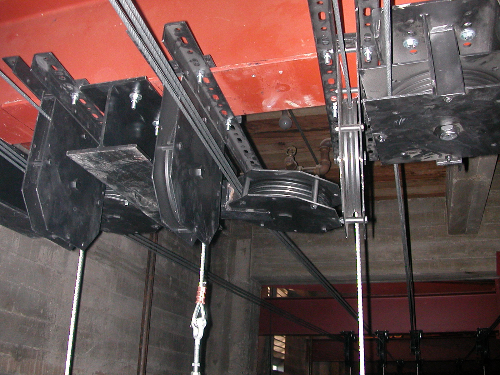
Blocks
 Grid-mount upright loft blocks
 Under-hung loft & mule blocks
A block is a pulley used to support and direct lift and operating lines. A block consists of a grooved wheel, known as a sheave (pronounced "shiv"), steel side plates, spacers, shaft, flange bearings, mounting angles and clips, etc. Blocks are sized based on anticipated live loads, operating speeds, line type and other factors. Sheaves were traditionally fabricated of cast iron, but steel and nylon sheaves are now common.
Blocks are either upright, when mounted atop a support structure, or under-hung, when mounted to the underside of a support structure.
The side plates of blocks preferably fully cover the profile of (fully enclose) the sheaves to lend the block greater stability and limit the sheave's (and crew's) potential for damage from foreign objects. Nevertheless, blocks are available with exposed sheaves.
- Loft block
A Loft block is an overhead block that supports a single lift line. A loft block supports and redirects a lift line from the batten to the head block of a line set. Under-hung loft blocks typically mount to loft block beams (fly loft roof beams). Upright loft blocks typically mount to loft block wells (grid-level structural channels). A spot block is a readily movable loft block for mounting anywhere on the grid deck for spot rigging.
The diameter of a loft block sheave for galvanized aircraft cable is typically at least 32 times the diameter of the cable. For example 8" loft blocks are typically used with 1/4" GAC, but 12" blocks may be used to facilitate flying heavier line sets (e.g. electrics).
Loft blocks may be equipped with idler pulleys or sag bars to limit the sag of horizontally running lift lines on under-hung systems.
In under-hung counterweight systems that use upright head blocks the series of loft blocks immediately following the head blocks are typically multi-line loft blocks instead of single-line to account for built-in vertical misalignment between head blocks and loft blocks.
 Under-hung head blocks
 Upright head blocks
- Head block
Head blocks are overhead multi-line blocks used for the lift lines and operating lines. Head blocks support and redirect all the lift lines from loft blocks to sand bags (of a hemp set), counterweight arbor (of a counterweight set) or hoist (of an automated line set).
Rope line (hemp) head blocks are typically upright blocks that mount to the rope line head block well channels at the grid level.
In a counterweight rigging system the head block sheave is grooved for both the steel cable lift lines and an operating line, with the groove for the operating line provided at the middle of the multi-grooved sheave, between the lift lines. Counterweight head blocks mount atop or at the underside of the head block beam, depending on the beam's vertical position.
The diameter of a head block sheave used for galvanized aircraft cable is typically at least 48 times the diameter of the cable. For example 12" head blocks are typically used with 1/4" GAC, but 16" blocks may be used to facilitate flying heavier line sets (e.g. electrics).
- Mule block
Lift lines sometimes require diversion to avoid obstacles, support non-linear loads and battens, deal with excessive fleet angles, or be reoriented from the typical transverse path across the stage (e.g. for tab and light ladder line sets). Mule blocks are single or multi-line blocks able to divert the path of those lines. Mule blocks may be permanently installed as part of counterweight rigging systems, or used for spot rigging, where they are often equipped with swivel-pivots to divert lines across a large range of angles.
- Tension block
Tension blocks are single-sheave blocks located at the lower end of the arbor guide track, beneath the arbor. The operating line is reeved through the tension block from the bottom of the arbor through the rope lock. Tension blocks typically ride vertically along the arbor guide system tracks, instead of being fixed, to allow for variation in the length of the operating line.
Counterweights
Counterweights are heavy objects that are used to balance the lineset loads in a fly system. In hemp systems, a counterweight consists of one or more sandbags, whereas counterweight systems employ metal bricks as counterweights. The term counterweight is commonly used to refer specifically to the metal counterweight bricks.
Metal counterweights are lead, cast iron, or flame-cut steel. Flame cut steel bricks are most common. In any particular fly system all counterweights typically share a common, standardized footprint that matches the system's arbors, which in turn are sized to conform to line set spacing. Counterweight systems are most often designed to use either 4 or 6-inch (150 mm) wide weights. Weights vary in thickness, typically in half-inch increments ranging from 1/2 to 2 inches (51 mm), with each thickness corresponding to a different mass. 1" thick weights are most common. Counterweights are sometimes also known as bricks or simply steel. Often a rigging worker will be asked to load a number of inches of steel, which correlates to a specific mass. Weights are usually loaded from the loading bridge, but can also be loaded from the fly gallery or stage deck in some circumstances.
When viewed from the top, metal counterweight is basically rectangular, typically with 45-degree angle chamfers cut at two opposing corners. A slot is cut into each end of the weight so as to enable the weight to straddle, and be laterally secured by, the arbor rods. In order to facilitate removal of weights with angle cuts, it is customary to stack the weights in alternating orientations so that the square corners of any weight will be aligned with the angled corners of adjacent weights. This simplifies removal because the protruding square corners of the topmost weight effectively serve as "handles" that can be easily gripped, even with gloved hands.
It is customary to apply paint (typically yellow) or colored tape to the weights that counterbalance the batten (pipe) to indicate that they should not be removed from the arbor. As an additional precaution, they may be strapped in with steel strapping. When a dedicated line set carries a permanent load (e.g. main drape, orchestra cloud, etc) the counterweight balancing the additional load may be treated in a similar fashion.
Standard cut steel weight schedule (in pounds)* Counterweight dimensions 4" x 13 ⅝" 5" x 13 ⅝" 6" x 13 ⅝" 8" x 13 ⅝" 10" x 24" Weight per inch 14.02 17.88 21.73 29.44 66.52 Weight per foot 168.24 214.56 260.76 353.28 798.24 * Steel to lead weight ratio is 1 : 1.448 Arbors
A counterweight arbor is a sturdy mechanical assembly that serves as a carriage for counterweights. In its simplest form, an arbor consists of two horizontal steel plates, a top plate and bottom plate, tied together by two vertical steel connecting rods. Counterweights are stacked as required on the arbor's bottom plate to balance the line set load, with the weights held in place by the connecting rods.
A flat tie bar at the rear of the arbor also connects the top and bottom plates. Guide shoes at the top and bottom of the tie bar guide the arbor along tracks mounted to the side stage wall. UHMWPE pads on the guide shoes limit friction between guide shoe and track as the arbor travels.
Spreader plates are thin steel plates with holes through which the arbor connecting rods pass. Spreader plates are lowered onto the counterweights in a distributed fashion as the counterweight stack is being built. Typically one spreader plate is placed on top of every two feet of counterweight in the stack. Finally, a locking plate is lowered onto the completed, interleaved stack of counterweights and spreader plates and secured in place with a thumbscrew.
Spreader plates serve to maintain consistent spacing between the arbor rods to ensure reliable containment of the counterweights under normal operating conditions. Also, in the event of a "runaway" (loss of control of an unbalanced lineset), the spreader plates will prevent the arbor rods from bending outward, and thus releasing the counterweights upon arbor impact at the end of its travel.
Counterweight arbors are commonly between 8 and 12 feet in length and can often support stacks of weights between 1500 and 2400 pounds, or beyond. In order to avoid unreasonably tall counterweight stacks at high capacity line sets, arbors may employ more than one counterweight stack. Such arbors use multiple-width top and bottom plates with a tie bar and pair of connecting rods provided at each counterweight stack.
Counterweight arbors  Counterweight arbor viewed from below. The guide rail can be seen at the rear of the arbor.
 A large counterweight arbor with multiple stacks.
 Top of an arbor, with attached lift lines visible.
 Spreader plates, used to maintain arbor rod spacing.
Counterweight rigging systems use either tracked or wire-guided arbor guide systems. The tracks or wire guides limit lateral movement of the arbors during arbor travel. Wire-guided systems have lower capacities and are not in common use.
In addition to guiding the arbors, a tracked counterweight system is provided with bump stops at arbor high and low trim that establish the limits of an arbor's travel.
A tracked guide system is sometimes referred to as a T-bar wall, as the tracks are commonly made of steel T-sections. Aluminum arbor guide tracks are a relatively recent alternative, often using a J profile, instead of a T profile, to facilitate system installation.
Hoists
Hoists of various types are used in manual automated rigging systems. The terms hoist and winch are often used interchangeably in theatre jargon. Hoists are generally assumed to be motorized unless "manual" is used as a descriptor.
- Manual hoist
Manual hoists, or hand winches, are typically composed of a drum, gear box, and crank (operating handle). A worm gear is commonly used to provide mechanical advantage as the crank is turned, which coils a single line around a smooth or helically-grooved drum. The drum line is connected to the lift lines with a clew, triangular plate with holes used for line terminations. From the clew, the lift lines run over a head block and loft blocks down to a batten. The clew may be wire-guided to limit lateral play. Drill-operable hand winches permit the handle to be removed so that an electric drill may operate the hoist.
- Drum hoist
Drum hoists are typically composed of an electric brake motor and a multi-line helically-grooved drum. Helical drums are preferable to smooth drums for cable longevity and the precise and repeatable control of travel.
Drum hoists are used for motor-assist, engaging an operating line, and dead-haul, engaging the lift lines, applications.
A dead-haul drum hoist uses the single drum to support all the lift lines running from the head block of a line set. The lift lines neatly wrap and unwrap in a side-by-side arrangement on the drum as it is spun by the motor.
As a lift line coils and uncoils from the drum of a drum hoist, its fleet angle (angle of a line between drum and sheave) changes. Excessive fleet angles (e.g. greater than 1 ½ or 2 degrees) cause unpredictable line behavior and can damage lines, blocks, and drums. As a result, fleet angles limit how close a dead-haul drum hoist can be mounted to the head block (usually about 10 feet).
A moving drum hoist, or traveling drum hoist, is a variation on the traditional drum hoist. Moving drum hoists effectively eliminate the fleet angle between drum and block by shifting the drum along its axis as it spins. The amount of shift per drum revolution is equal to the pitch of the drum's helical groove. With the fleet angle problem resolved, moving drum hoists can combine drum and head block into a single, relatively compact, unit for mounting to fly loft structure, with a corresponding reduction of installation cost.
- Line shaft hoist
 Drum on a line shaft hoist
Line shaft hoists are typically composed of an electric brake motor, line shaft (drive shaft) and evenly spaced single-line drums aligned above the batten pick points. By placing an individual drum over each pick point, line shaft sets have the advantage, over drum sets, of eliminating the need for blocks.
To avoid lateral drift of the batten as the lift lines pay out of the grooved drums, the helical groove orientation on the drums of the line shaft may be alternated between drums to balance competing fleet angles. However the elimination of drift by this method is typically compromised by limited batten travel.
Yo-yo, pile-up, or pilewind, hoists are typically line shaft hoists that use yo-yo type devices instead of helically grooved drums. Yo-yo hoists are typically used where lighter loads are imposed (e.g. for operating an Austrian puff curtain). Because yo-yos lines pile-up (coil) into overlapping layers of cable, the velocity and travel of the lines are relatively difficult to accurately control.
- Point hoist
Point hoists, also known as spot line winches, control a single lift line and are commonly used for automated spot rigging or flying rigs. A point hoist may operate in solitude, or in unison with other point hoists to comprise a line set.
Chain hoists, more commonly referred to as chain motors, are the most common form of point hoist, especially with touring musical shows (e.g. rock-and-roll shows), but are relatively slow. Chain motors can be mounted at the grid to hoist a load from above, or mounted at the load to "climb" towards the grid.
Point hoists using wire rope (GAC) are common, and steel band point hoists are also used. While generally more expensive than chain hoists, wire rope and steel band point hoists can operate at relatively high speeds. Wire rope spot line winches may pay out to the side, for use with a loft block, so that only the block need be spotted above the pick point (instead of the entire winch).
Fly system infrastructure
Fly system infrastructure consists of the relatively permanent load-bearing and load-transferring structures of a stage house. The infrastructure, generally fabricated of structural steel members, is sized by a structural engineer during the design of a new theatre, or theatre renovation. Rigging system infrastructure ultimately limits a fly system's capacity.
Building codes generally require that fly system beam design meets the L/360 rule: beams shall not deflect by more than the length of a span divided by 360. For example, a 30-foot head block beam should not deflect more than 1 inch under the system design's maximum loading condition. Beam design using the L/360 rule typically results in beams with a yield-strength significantly higher than the maximum loading condition, effectively providing a factor of safety.
 Linesets are manually operated from a locking rail such as this one.
 Loading bridge. Weights are seen on floor.
 Grid-less fly tower with catwalks. Battens (yellow), under-hung blocks and lift lines are visible.
 Channel-type grid with upright blocks and lift lines visible.
 Channel-type grid, viewed from below with drapes, battens, and electrics visible.
 Upright loft blocks on a channel-type grid.
Fly loft
The fly loft, fly tower or fly space, is the large volume above the stage into which line set battens are flown, along with whatever load they may be carrying. In a full size fly space, the tower is preferably at least 2.5 times as tall as the proscenium, to allow a full-height set piece to be stored completely out of view of the audience while providing adequate travel distance for standard (single-purchase) counterweight arbors.
Grid deck
 Underhung system with grid
 Underhung system without grid
The grid deck, gridiron deck, or grid, is a permeable working surface present at the top of many fly lofts that is used to support and provide access to many of a rigging system's components. Though originally constructed of wood, down-facing three-inch steel channels with three-inch gaps became the prevalent grid decking in the 20th century. Today, large-opening heavy-duty steel bar grating is most common in new theatres. The grid deck surface is usually rated to support live loads as well as all anticipated dead-hung equipment and hemp and motorized (e.g. chain hoist) spot rigging. Its permeability facilitates the mounting of equipment and the passing of lift lines and electrical cables. Spot rigging is not feasible without a grid.
The grid deck allows access to the "head block beam" and "loft block beams" of counterweight systems. Spanning from the proscenium wall to the upstage wall, these beams support the dead and live loads of a fly system. As per their names, counterweight system head blocks and loft blocks may be directly mounted to these beams. The head block beam is situated directly above the loading gallery. The loft block beams are spaced to match the "pick points" of the lift lines suspending the battens. The loft block beams may also be used to suspend the grid deck support structure.
Rope line (hemp) head block well channels sit atop the grid deck and are used for mounting hemp system head blocks. They are situated above the pinrail(s) below.
Loft block wells are ten inch gaps between pairs of face-to-face steel channels flush with the grid deck that occur beneath each loft block beam. The loft blocks of a hemp, or grid-mount counterweight, rigging system can mount to the loft block well channels. The loft block wells may also act as clear openings through which the lift lines of under-hung counterweight, or automated, systems may pass.
A grid deck is indispensable in professional and touring theatres, and desirable in all theatres with a fly tower, providing invaluable access and flexibility to fly systems. However, due to height limitations, not all fly towers are equipped with a grid. Transverse catwalks are sometimes provided as compensation for the lack of a grid. San Francisco's War Memorial Opera House, not burdened by height limitations, has two grid decks.
Loading bridge
Specific to a stage house using a counterweight system, the loading bridge, or loading gallery, is a catwalk vertically positioned below the headlock beam, and above the fly gallery. The loading bridge is used to add or remove counterweights from arbors. The floor of the loading bridge is also typically used as a storage area for uncommitted counterweights that are available for loading onto counterweight arbors. Stage houses with especially tall fly towers, or double-purchase systems, may have two loading bridges, one stacked over the other to facilitate the loading of relatively tall arbors.
Fly gallery
A fly gallery is a catwalk running from the proscenium wall to upstage wall to which a pinrail and/or locking rail may be mounted used by the fly crew to operate the fly system. The fly gallery elevation is typically at about proscenium height, providing a good view of the stage and fly loft. Fly galleries may be provided stage left and right, or at just one side. Where provided at both sides of the stage they may be connected by a cross-over catwalk at the upstage wall. It is possible to load arbors (add or remove counterweights) at the fly gallery, but standard practice is to load arbors at the loading bridge.
Pin rail
 A pin-rail above stage level.
A pin rail, originally a wood beam, is typically a large-diameter round steel tube with vertical through-holes that accept belaying pins used in a hemp rigging system. Depending on the pin rail design, the pins may be removable or permanently fixed to the rail. Pin rails are typically installed permanently at the onstage edge of the fly gallery(ies), extending from the proscenium wall to upstage wall, sometimes in a stacked (rail over rail) arrangement. Mobile pin rails may also be used and are bolted down to the stage deck where needed.
Locking rail
 Locking rail with arbors, counterweights, rope locks (red) and pins for spot lines visible.
A locking rail is typically a steel angle or rectangular tube to which the rope locks of a counterweight system are mounted. Locking rails are located on the stage deck and/or fly gallery and typically extend from the proscenium wall to the upstage wall.
A stage-level locking rail may be provided with an engaging bar for a portable capstan winch.
Arbor pit
Arbor pits, where provided, are troughs at the stage edge that provide additional vertical travel to a counterweight system's arbors. Providing a counterweight arbor pit can help compensate for height limitations of a fly tower. The trough depth typically ranges from 2 to 10 feet. Shallower pits may be accessible only from above at the stage deck. Deeper pits are sometimes accessible from a trap room or orchestra pit.
Operation
Because fly systems involve large amounts of weight, and particularly because the weight is usually suspended above people, there are a number of common precautions taken to ensure safety and prevent injuries. Communication, inspection, and loading procedure are key to the safe operation of a fly system.
Calling movement
Except for during performances and some rehearsals, a standard practice in theatre is for the flyman to always call (shout) out a warning before moving a lineset so as to alert personnel (e.g., rehearsing performers and technicians) who are on the stage. People on stage typically acknowledge the operator's warning by yelling out a confirmation that the warning was heard.
The flyman's warning specifies what is moving and its direction of movement. For example, a particularly verbose call might be something like "lineset three, first electric flying in to the deck, downstage" (in USA) or "Heads onstage, Bar 3, LX 1 coming in." (in UK). In many theaters, all people on stage are expected to respond with "thank you." Upon completion of the lineset motion, some operators may call again (e.g., "lineset three locked") to announce that the lineset has stopped moving.
Unbalanced loads
Unbalanced loads are of great concern in manual rigging. Minor imbalance is sometimes desirable, for example so that as an operating line is let out a line set will fly in of its own accord. However, as it is common for many thousands of pounds of equipment and scenery to be flown above cast and crew, major imbalance is a grave hazard, and, if left unaddressed, can result in runaways.
The use of block and tackle or capstan winch is common to handle line sets that have significantly unbalanced loads. Block and tackle sets use the mechanical advantage (e.g. 6 : 1) of multi-purchase blocks to enable a crew to manually raise an imbalanced line set. The standing block is secured at the grid level and the running block to the batten or arbor (whichever is overloaded). Where an engaging bar has been designed into the stage level locking rail, a portable electric capstan winch may be used to counteract an imbalanced counterweight line set. Pulling on (constricting) a rope wrapped a few times around the capstan, a drum spinning at a constant rate, generates enough traction (through friction) to tug the imbalanced load.
Especially tall fly towers pose a balance problem for standard counterweight line sets. As a line set is lowered to the stage, the weight of the lift lines is added to the total weight of the line set that a rigger must be able to control. For example, a batten with 6 lift lines of ¼” aircraft cable that travels 50 feet effectively weighs about 40 pounds more when flown in than when it is flown out. To address this issue compensating chains may be built into the counterweight system. One end of the compensating chain (typically roller chain) is suspended from the underside of the counterweight arbor, the opposite end mounted to the adjacent wall, at a point corresponding to half the travel of the arbor. The compensating chain is about half the length that the arbor travels, and sized to weigh twice as much as the combined weight of the lift lines per linear foot. At arbor low trim, the compensating chain is fully supported by the wall. At arbor high trim, the chain is fully supported by the arbor. Paying out at half the speed of arbor travel, a compensating chain effectively eliminates imbalance along the full path of travel.
Runaways
A runaway is a moving lineset that cannot be safely controlled by its operator. Runaways can occur when the weight on the arbor is not equal to the weight of the batten and its load. Linesets are often intentionally unbalanced to facilitate quick flying in one direction and, in such cases, runaways are more likely to occur.
In the rare event that an unbalanced lineset gains so much momentum that the operator cannot stop it, a specified safety procedure is usually followed. Venues typically establish a standard call for this event, which might sound something like "Runaway 47, upstage, heads." Operators are trained not to attempt to stop a runaway lineset but rather to warn others and safely escape. The reason for this is that it is unlikely that they will be able to stop it, and very likely that they will burn their hands or be lifted up by the lineset, potentially injuring themselves on the structure above them. Furthermore, this might position the operator in the path of the batten, arbor, or sandbag as they accelerate downward. Spreader plates are used in counterweight arbors to keep the arbor's vertical rods from bending and releasing the counterweights in the event of a runaway, while the locking plate prevents the counterweights from bouncing out of the arbor.
Counterweight system loading procedure
When loading a batten, or arbor in a counterweight system, it is imperative to control the balance of a set. The lineset should be balanced before loading begins, then the batten flown in, the set added, and then the counterweight added from the loading bridge. The specific order is important because it keeps the set from being unbalanced in a position where it could run away. When it is batten-heavy (after the set is added, but before the counterweights) the arbor does not have anywhere to run away to as it is already at its grid stop (the upper end of the track). In cases where the set is too tall for the batten to be all the way in, it should be kept as far down as possible. It is always best to add the load in pieces as small as practical and counterweight them one at a time so the system can never get too out of balance. Improper loading procedure is a common cause of accidents in many theaters.
References
- ^ Gillette (1981). Stage Scenery (Third ed.). Harper and Row. ISBN 0060423323.
- ^ Gillette, J. Michael (2003). Designing With Light: An Introduction to Stage Lighting, Fourth Edition". McGraw Hill. p. 84. ISBN 0-7674-2733-5.
- ^ Jay O. Glerum (2007). Stage Rigging Handbook, Third Edition. Southern Illinois University Press. p. 65. ISBN 978-0809327416.
- ^ a b J. Michael Gillette (2000). Theatrical Design and Production, Fourth Edition. Mayfield Publishing Company. p. 56. ISBN 0=7674-1191-9.
Stagecraft Theatrical scenery
(Scene shop)FieldsHardwareStage lighting FieldsHardwareBarn doors · Color gel · Color scroller · Cyclorama · Gobo · Lighting control console · Stage pin connector · Top hat · Theatrical fogBeam projector · Ellipsoidal reflector spotlight · Fresnel lantern · Intelligent lighting · Parabolic aluminized reflector light · Scoop · Striplight · AccessoriesOther Fields Categories:- Fly system
- Stagecraft
- Parts of a theatre
- Stage terminology


Wikimedia Foundation. 2010.