- Mismatch loss
-
Mismatch loss in transmission line theory is the amount of power expressed in decibels that will not be available on the output due to impedance mismatches and reflections. A transmission line that is properly terminated, that is, terminated with the same impedance as that of the characteristic impedance of the transmission line, will have no reflections and therefore no mismatch loss. Mismatch loss represents the amount of power wasted in the system. It can also be thought of as the amount of power gained if the system was perfectly matched. Impedance matching is an important part of RF system design; however, in practice there will likely be some degree of mismatch loss.[1] In real systems, relatively little loss is due to mismatch loss and is often on the order of 1dB.
Contents
Calculation
Mismatch loss (ML) is the ratio of incident power to the difference between incident and reflected power:
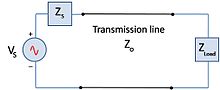 Figure 1. Simple circuit showing characteristic impedance Zo and the load impedance ZL. In a perfectly matched system ZL=Zo, and there is no mismatch loss.
where
Pi = incident power
Pr = reflected power
Pd = delivered power (also called the accepted power)The fraction of incident power delivered to the load is
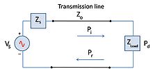 Figure 2. Simple circuit showing incident power, Pi, on a load. The reflected power will be the difference between Pi and the power delivered, Pd.
where ρ is the magnitude of the reflection coefficient. Note that as the reflection coefficient approches zero, power to the load is maximized.If the reflection coefficient is known, mismatch can be calculated by
In terms of the voltage standing wave ratio (VSWR):
Sources of mismatch loss
Any component of the transmission line that has an input and output will contribute to the overall mismatch loss of the system. For example, in mixers mismatch loss occurs when there is an impedance mismatch between the RF port and IF port of the mixer.[2] This is one of the principal reasons for losses in mixers. Likewise, a large amount of the loss in amplifiers comes from the mismatch between the input and output. Consequently, not all of the available power generated by the amplifier gets transferred to the load.[3] This is most important in antenna systems where mismatch loss in the transmitting and receiving antenna directly contributes to the losses the system—including the system noise figure. Other common RF system components such as filters, attenuators, splitters, and combiners will generate some amount of mismatch loss. While completely eliminating mismatch loss in these components is near impossible, mismatch loss contributions by each component can be minimized by selecting quality components for use in a well designed system.
Mismatch error
[4] If there are two or more components in cascade as is often the case, the resultant mismatch loss is not only due to the mismatches from the individual components, but also from how the reflections from each component combine with each other. The overall mismatch loss cannot be calculated by just adding up the individual loss contributions from each component. The difference between the sum of the mismatch loss in each component and total mismatch loss due to the interactions of the reflections is known as mismatch error. Depending on how the multiple reflections combine, the overall system loss may be lower or higher than the sum of the mismatch loss from each component. Mismatch error occurs in pairs as the signal reflects off of each mismatched component. So for the example in Figure 3, there are mismatch errors generated by each pair of components.[5] The mismatch uncertainty increases as the frequency increases, and in wide-band applications. The phasing of the reflections makes it particularly harder to model.
The general case for calculating mismatch error (ME) is:
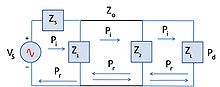 Figure 3. Simple circuit showing multiple reflections due to more than 1 mismatched device.
where θ is the complex phase change due to the second reflection
See also
References
- ^ Daniels, David J. (2004). Ground penetrating radar (2nd Edition). Institution of Engineering and Technology. ISBN 978-0-86341-360-5
- ^ Carr, Joseph J. (2002). RF components and circuits. Oxford: Newnes. ISBN 0 7506 48449
- ^ Skolnik, Merrill I. (2001). Introduction to radar systems (3rd Edition). New York: McGraw-Hill. ISBN 0-07-288138-0
- ^ White, Joseph F. (2004). High frequency techniques: An introduction to RF and microwave engineering. Hoboken: Wiley. ISBN 0471455911
- ^ Briggs, John N. (2004). Target detection by marine radar. Institution of Engineering and Technology. ISBN 978-0-86341-359-9
Categories:- Telecommunications


Wikimedia Foundation. 2010.