- Jet engine
-
For a general overview of aircraft engines, see Aircraft engine.
 A Pratt & Whitney F100 turbofan engine for the F-15 Eagle being tested in the hush house at Florida Air National Guard base. The tunnel behind the engine muffles noise and allows exhaust to escape
 Simulation of a low bypass turbofan's airflow
A jet engine is a reaction engine that discharges a fast moving jet to generate thrust by jet propulsion and in accordance with Newton's laws of motion. This broad definition of jet engines includes turbojets, turbofans, rockets, ramjets, pulse jets. In general, most jet engines are internal combustion engines[1] but non-combusting forms also exist.
In common parlance, the term jet engine loosely refers to an internal combustion airbreathing jet engine (a duct engine). These typically consist of an engine with a rotary (rotating) air compressor powered by a turbine ("Brayton cycle"), with the leftover power providing thrust via a propelling nozzle. These types of jet engines are primarily used by jet aircraft for long distance travel. Early jet aircraft used turbojet engines which were relatively inefficient for subsonic flight. Modern subsonic jet aircraft usually use high-bypass turbofan engines which give high speeds, as well as (over long distances) fuel efficiency that is about as good as piston and propeller aeroengines.[2]
Contents
History
Main article: History of the jet engineSee also: Timeline of jet powerJet engines can be dated back to the invention of the aeolipile before the first century AD. This device used steam power directed through two nozzles to cause a sphere to spin rapidly on its axis. So far as is known, it was not used for supplying mechanical power, and the potential practical applications of this invention were not recognized. It was simply considered a curiosity.
Jet propulsion only took off, literally and figuratively, with the invention of the gunpowder-powered rocket by the Chinese in the 13th century as a type of fireworks, and gradually progressed to propel formidable weaponry. However, although very powerful, at reasonable flight speeds rockets are very inefficient and so jet propulsion technology stalled for hundreds of years.
The earliest attempts at airbreathing jet engines were hybrid designs in which an external power source first compressed air, which was then mixed with fuel and burned for jet thrust. In one such system, called a thermojet by Secondo Campini but more commonly, motorjet, the air was compressed by a fan driven by a conventional piston engine. Examples of this type of design were the Caproni Campini N.1, and the Japanese Tsu-11 engine intended to power Ohka kamikaze planes towards the end of World War II. None were entirely successful and the N.1 ended up being slower than the same design with a traditional engine and propeller combination.

Even before the start of World War II, engineers were beginning to realize that the piston engine was self-limiting in terms of the maximum performance which could be attained; the limit was due to issues related to propeller efficiency,[3] which declined as blade tips approached the speed of sound. If engine, and thus aircraft, performance were ever to increase beyond such a barrier, a way would have to be found to radically improve the design of the piston engine, or a wholly new type of powerplant would have to be developed. This was the motivation behind the development of the gas turbine engine, commonly called a "jet" engine, which would become almost as revolutionary to aviation as the Wright brothers' first flight.
The key to a practical jet engine was the gas turbine, used to extract energy from the engine itself to drive the compressor. The gas turbine was not an idea developed in the 1930s: the patent for a stationary turbine was granted to John Barber in England in 1791. The first gas turbine to successfully run self-sustaining was built in 1903 by Norwegian engineer Ægidius Elling. Limitations in design and practical engineering and metallurgy prevented such engines reaching manufacture. The main problems were safety, reliability, weight and, especially, sustained operation.
The first patent for using a gas turbine to power an aircraft was filed in 1921 by Frenchman Maxime Guillaume.[4] His engine was an axial-flow turbojet. Alan Arnold Griffith published An Aerodynamic Theory of Turbine Design in 1926 leading to experimental work at the RAE.
 The Whittle W.2/700 engine flew in the Gloster E.28/39, the first British aircraft to fly with a turbojet engine, and the Gloster Meteor
In 1928, RAF College Cranwell cadet [5] Frank Whittle formally submitted his ideas for a turbo-jet to his superiors. In October 1929 he developed his ideas further.[6] On 16 January 1930 in England, Whittle submitted his first patent (granted in 1932).[7] The patent showed a two-stage axial compressor feeding a single-sided centrifugal compressor. Practical axial compressors were made possible by ideas from A.A.Griffith in a seminal paper in 1926 ("An Aerodynamic Theory of Turbine Design"). Whittle would later concentrate on the simpler centrifugal compressor only, for a variety of practical reasons. Whittle had his first engine running in April 1937. It was liquid-fuelled, and included a self-contained fuel pump. Whittle's team experienced near-panic when the engine would not stop, accelerating even after the fuel was switched off. It turned out that fuel had leaked into the engine and accumulated in pools, so the engine would not stop until all the leaked fuel had burned off. Whittle was unable to interest the government in his invention, and development continued at a slow pace.
 Heinkel He 178, the world's first aircraft to fly purely on turbojet power
In 1935 Hans von Ohain started work on a similar design in Germany, apparently unaware of Whittle's work.[8] His first device was strictly experimental and could only run under external power, but he was able to demonstrate the basic concept. Ohain was then introduced to Ernst Heinkel, one of the larger aircraft industrialists of the day, who immediately saw the promise of the design. Heinkel had recently purchased the Hirth engine company, and Ohain and his master machinist Max Hahn were set up there as a new division of the Hirth company. They had their first HeS 1 centrifugal engine running by September 1937. Unlike Whittle's design, Ohain used hydrogen as fuel, supplied under external pressure. Their subsequent designs culminated in the gasoline-fuelled HeS 3 of 1,100 lbf (5 kN), which was fitted to Heinkel's simple and compact He 178 airframe and flown by Erich Warsitz in the early morning of August 27, 1939, from Rostock-Marienehe aerodrome, an impressively short time for development. The He 178 was the world's first jet plane.[9]
 A cutaway of the Junkers Jumo 004 engine
Austrian Anselm Franz of Junkers' engine division (Junkers Motoren or Jumo) introduced the axial-flow compressor in their jet engine. Jumo was assigned the next engine number in the RLM 109-0xx numbering sequence for gas turbine aircraft powerplants, "004", and the result was the Jumo 004 engine. After many lesser technical difficulties were solved, mass production of this engine started in 1944 as a powerplant for the world's first jet-fighter aircraft, the Messerschmitt Me 262 (and later the world's first jet-bomber aircraft, the Arado Ar 234). A variety of reasons conspired to delay the engine's availability, causing the fighter to arrive too late to improve Germany's position in World War II. Nonetheless, it will be remembered as the first use of jet engines in service.
Meanwhile, in Britain the Gloster E28/39 had its maiden flight on 15 May 1941 and the Gloster Meteor finally entered service with the RAF in July 1944.
Following the end of the war the German jet aircraft and jet engines were extensively studied by the victorious allies and contributed to work on early Soviet and US jet fighters. The legacy of the axial-flow engine is seen in the fact that practically all jet engines on fixed wing aircraft have had some inspiration from this design.
By the 1950s the jet engine was almost universal in combat aircraft, with the exception of cargo, liaison and other specialty types. By this point some of the British designs were already cleared for civilian use, and had appeared on early models like the de Havilland Comet and Avro Canada Jetliner. By the 1960s all large civilian aircraft were also jet powered, leaving the piston engine in low-cost niche roles such as cargo flights.
The efficiency of turbojet engines was still rather worse than piston engines but by the 1970s, with the advent of high bypass turbofan jet engines, an innovation not foreseen by the early commentators such as Edgar Buckingham, at high speeds and high altitudes that seemed absurd to them, fuel efficiency was about the same as the best piston and propeller engines.[2]
Uses
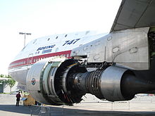 A JT9D turbofan jet engine undergoing maintenance on a Boeing 747 aircraft
Jet engines are usually used as aircraft engines for jet aircraft. They are also used for cruise missiles and unmanned aerial vehicles.
In the form of rocket engines they are used for fireworks, model rocketry, spaceflight, and military missiles.
Jet engines have also been used to propel high speed cars, particularly drag racers, with the all-time record held by a rocket car. A turbofan powered car ThrustSSC currently holds the land speed record.
Jet engine designs are frequently modified for non-aircraft applications, as industrial gas turbines. These are used in electrical power generation, for powering water, natural gas, or oil pumps, and providing propulsion for ships and locomotives. Industrial gas turbines can create up to 50,000 shaft horsepower. Many of these engines are derived from older military turbojets such as the Pratt & Whitney J57 and J75 models. There is also a derivative of the P&W JT8D low-bypass turbofan that creates up to 35,000 HP.
Types
There are a large number of different types of jet engines, all of which achieve forward thrust from the principle of jet propulsion.
Airbreathing
Main article: Airbreathing jet engineCommonly aircraft are propelled by airbreathing jet engines. Most airbreathing jet engines that are in use are turbofan jet engines which give good efficiency at speeds just below the speed of sound.
Turbine powered
Main article: Gas turbineGas turbines are rotary engines that extract energy from a flow of combustion gas. They have an upstream compressor coupled to a downstream turbine with a combustion chamber in-between. In aircraft engines, those three core components are often called the "gas generator."[10] There are many different variations of gas turbines, but they all use a gas generator system of some type.
Turbojet
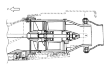
Main article: Turbojet Turbojet engine
A turbojet engine is a gas turbine engine that works by compressing air with an inlet and a compressor (axial, centrifugal, or both), mixing fuel with the compressed air, burning the mixture in the combustor, and then passing the hot, high pressure air through a turbine and a nozzle. The compressor is powered by the turbine, which extracts energy from the expanding gas passing through it. The engine converts internal energy in the fuel to kinetic energy in the exhaust, producing thrust. All the air ingested by the inlet is passed through the compressor, combustor, and turbine, unlike the turbofan engine described below.[11]
Turbofan
 Schematic diagram illustrating the operation of a low-bypass turbofan engine.Main article: Turbofan
A turbofan engine is a gas turbine engine that is very similar to a turbojet. Like a turbojet, it uses the gas generator core (compressor, combustor, turbine) to convert internal energy in fuel to kinetic energy in the exhaust. Turbofans differ from turbojets in that they have an additional component, a fan. Like the compressor, the fan is powered by the turbine section of the engine. Unlike the turbojet, some of the flow accelerated by the fan bypasses the gas generator core of the engine and is exhausted through a nozzle. The bypassed flow is at lower velocities, but a higher mass, making thrust produced by the fan more efficient than thrust produced by the core. Turbofans are generally more efficient than turbojets at subsonic speeds, but they have a larger frontal area which generates more drag.[12]
There are two general types of turbofan engines, low bypass and high bypass. Low bypass turbofans have a bypass ratio of around 2:1 or less, meaning that for each kilogram of air that passes through the core of the engine, two kilograms or less of air bypass the core.[citation needed] Low bypass turbofans often used a mixed exhaust nozzle meaning that the bypassed flow and the core flow exit from the same nozzle.[13] High bypass turbofans have larger bypass ratios, sometimes on the order of 5:1 or 6:1. These turbofans can produce much more thrust than low bypass turbofans or turbojets because of the large mass of air that the fan can accelerate, and are often more fuel efficient than low bypass turbofans or turbojets.[citation needed]
Turboprop and turboshaft
Main articles: Turboprop and Turboshaft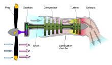 Turboprop engine
Turboprop engines are jet engine derivatives that extract work from the hot-exhaust jet to turn a rotating shaft, which is then used to produce thrust by some other means. While not strictly jet engines in that they rely on an auxiliary mechanism to produce thrust, turboprops are very similar to other turbine-based jet engines, and are often described as such.
In turboprop engines, a portion of the engines' thrust is produced by spinning a propeller, rather than relying solely on high-speed jet exhaust. As their jet thrust is augmented by a propeller, turboprops are occasionally referred to as a type of hybrid jet engine. While many turboprops generate the majority of their thrust with the propeller, the hot-jet exhaust is an important design point, and maximum thrust is obtained by matching thrust contributions of the propeller to the hot jet.[14] Turboprops generally have better performance than turbojets or turbofans at low speeds where propeller efficiency is high, but become increasingly noisy and inefficient at high speeds.[15]
Turboshaft engines are very similar to turboprops, differing in that nearly all energy in the exhaust is extracted to spin the rotating shaft. They therefore generate little to no jet thrust. Turboshaft engines are often used to power helicopters.[13]
Propfan
Main article: Propfan A propfan engine
A propfan engine (also called "unducted fan", "open rotor", or "ultra-high bypass") is a jet engine that uses its gas generator to power an exposed fan, similar to turboprop engines. Like turboprop engines, propfans generate most of their thrust from the propeller and not the exhaust jet. The primary difference between turboprop and propfan design is that the propeller blades on a propfan are highly swept to allow them to operate at speeds around Mach 0.8, which is competitive with modern commercial turbofans. These engines have the fuel efficiency advantages of turboprops with the performance capability of commercial turbofans.[16] While significant research and testing (including flight testing) has been conducted on propfans, no propfan engines have entered production.
Ram powered
Ram powered jet engines are airbreathing engines similar to gas turbine engines and they both follow the Brayton cycle. Gas turbine and ram powered engines differ, however, in how they compress the incoming airflow. Whereas gas turbine engines use axial or centrifugal compressors to compress incoming air, ram engines rely only on air compressed through the inlet or diffuser.[17] Ram powered engines are considered the most simple type of air breathing jet engine because they can contain no moving parts.[18]
Ramjet
Main article: Ramjet A schematic of a ramjet engine, where "M" is the Mach number of the airflow.
Ramjets are the most basic type of ram powered jet engines. They consist of three sections; an inlet to compressed oncoming air, a combustor to inject and combust fuel, and a nozzle expel the hot gases and produce thrust. Ramjets require a relatively high speed to efficiently compress the oncoming air, so ramjets cannot operate at a standstill and they are most efficient at supersonic speeds. A key trait of ramjet engines is that combustion is done at subsonic speeds. The supersonic oncoming air is dramatically slowed through the inlet, where it is then combusted at the much slower, subsonic, speeds.[17] The faster the oncoming air is, however, the less efficient it becomes to slow it to subsonic speeds. Therefore ramjet engines are limited to approximately Mach 5.[19]
Scramjet
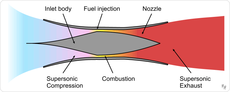
Main article: Scramjet Scramjet engine operation
Scramjets are mechanically very similar to ramjets. Like a ramjet, they consist of an inlet, a combustor, and a nozzle. The primary difference between ramjets and scramjets is that scramjets do not slow the oncoming airflow to subsonic speeds for combustion, they use supersonic combustion instead. The name "scramjet" comes from "supersonic combusting ramjet." Since scramjets use supersonic combustion they can operate at speeds above Mach 6 where traditional ramjets are too inefficient. Another difference between ramjets and scramjets comes from how each type of engine compresses the oncoming air flow: while the inlet provides most of the compression for ramjets, the high speeds at which scramjets operate allow them to take advantage of the compression generated by shock waves, primarily oblique shocks.[20]
Very few scramjet engines have ever been built and flown. In May 2010 the Boeing X-51 set the endurance record for the longest scramjet burn at over 200 seconds.[21]
Non-continuous combustion
Type Description Advantages Disadvantages Motorjet Obsolete type that worked like a turbojet but instead of a turbine driving the compressor a piston engine drives it. Higher exhaust velocity than a propeller, offering better thrust at high speed Heavy, inefficient and underpowered. Example: Caproni Campini N.1. Pulsejet Air is compressed and combusted intermittently instead of continuously. Some designs use valves. Very simple design, commonly used on model aircraft Noisy, inefficient (low compression ratio), works poorly on a large scale, valves on valved designs wear out quickly Pulse detonation engine Similar to a pulsejet, but combustion occurs as a detonation instead of a deflagration, may or may not need valves Maximum theoretical engine efficiency Extremely noisy, parts subject to extreme mechanical fatigue, hard to start detonation, not practical for current use Rocket
Main article: Rocket engine Rocket engine propulsion
The rocket engine uses the same basic physical principles as the jet engine for propulsion via thrust, but is distinct in that it does not require atmospheric air to provide oxygen; the rocket carries all components of the reaction mass.
This type of engine is used for launching satellites, space exploration and manned access, and permitted landing on the moon in 1969.
Rocket engines are used for high altitude flights as they have a lack of reliance on atmospheric oxygen and this allows them to operate at arbitrary altitudes, or anywhere where very high accelerations are needed since rocket engines themselves have a very high thrust-to-weight ratio.
However, the high exhaust speed and the heavier, oxidizer-rich propellant results in far more propellant use than turbofans although, even so, at extremely high speeds they become energy-efficient.
An approximate equation for the net thrust of a rocket engine is:
Where F is the thrust, Isp(vac) is the specific impulse, g0 is a standard gravity,
 is the propellant flow in kg/s, Ae is the area of the exhaust bell at the exit, and P is the atmospheric pressure.
Type Description Advantages Disadvantages Rocket Carries all propellants and oxidants on-board, emits jet for propulsion[22] Very few moving parts, Mach 0 to Mach 25+, efficient at very high speed (> Mach 5.0 or so), thrust/weight ratio over 100, no complex air inlet, high compression ratio, very high speed (hypersonic) exhaust, good cost/thrust ratio, fairly easy to test, works in a vacuum-indeed works best exoatmospheric which is kinder on vehicle structure at high speed, fairly small surface area to keep cool, and no turbine in hot exhaust stream. Very high temperature combustion and high expansion ratio nozzle gives very high efficiency- at very high speeds. Needs lots of propellant- very low specific impulse—typically 100–450 seconds. Extreme thermal stresses of combustion chamber can make reuse harder. Typically requires carrying oxidizer on-board which increases risks. Extraordinarily noisy. Hybrid
Combined cycle engines simultaneously use 2 or more different jet engine operating principles.
Type Description Advantages Disadvantages Turborocket A turbojet where an additional oxidizer such as oxygen is added to the airstream to increase maximum altitude Very close to existing designs, operates in very high altitude, wide range of altitude and airspeed Airspeed limited to same range as turbojet engine, carrying oxidizer like LOX can be dangerous. Much heavier than simple rockets. Air-augmented rocket Essentially a ramjet where intake air is compressed and burnt with the exhaust from a rocket Mach 0 to Mach 4.5+ (can also run exoatmospheric), good efficiency at Mach 2 to 4 Similar efficiency to rockets at low speed or exoatmospheric, inlet difficulties, a relatively undeveloped and unexplored type, cooling difficulties, very noisy, thrust/weight ratio is similar to ramjets. Precooled jets / LACE Intake air is chilled to very low temperatures at inlet in a heat exchanger before passing through a ramjet and/or turbojet and/or rocket engine. Easily tested on ground. Very high thrust/weight ratios are possible (~14) together with good fuel efficiency over a wide range of airspeeds, Mach 0-5.5+; this combination of efficiencies may permit launching to orbit, single stage, or very rapid, very long distance intercontinental travel. Exists only at the lab prototyping stage. Examples include RB545, Reaction Engines SABRE, ATREX. Requires liquid hydrogen fuel which has very low density and requires heavily insulated tankage. Water jet
Main article: Pump-jetA water jet, or pump jet, is a marine propulsion system that utilizes a jet of water. The mechanical arrangement may be a ducted propeller with nozzle, or a centrifugal compressor and nozzle.
 A pump jet schematic.
Type Description Advantages Disadvantages Water jet For propelling water rockets and jetboats; squirts water out the back through a nozzle In boats, can run in shallow water, high acceleration, no risk of engine overload (unlike propellers), less noise and vibration, highly maneuverable at all boat speeds, high speed efficiency, less vulnerable to damage from debris, very reliable, more load flexibility, less harmful to wildlife Can be less efficient than a propeller at low speed, more expensive, higher weight in boat due to entrained water, will not perform well if boat is heavier than the jet is sized for General physical principles
All jet engines are reaction engines that generate thrust by emitting a jet of fluid rearwards at relatively high speed. The forces on the inside of the engine needed to create this jet give a strong thrust on the engine which pushes the craft forwards.
Jet engines make their jet from propellant from tankage that is attached to the engine (as in a 'rocket') as well as in duct engines (those commonly used on aircraft) by ingesting an external fluid (very typically air) and expelling it at higher speed.
Propelling nozzle
The propelling nozzle is the key component of all jet engines as it creates the exhaust jet. Propelling nozzles turn pressurized, slow moving, usually hot gas, into lower pressure, fast moving, colder gas by adiabatic expansion.[23] Propelling nozzles can be subsonic, sonic, or supersonic,[24] but in normal operation nozzles are usually sonic or supersonic. Nozzles operate to constrict the flow, and hence help raise the pressure in the engine, and physically the nozzles are very typically convergent, or convergent-divergent. Convergent-divergent nozzles can give supersonic jet velocity within the divergent section, whereas in a convergent nozzle the exhaust fluid cannot exceed the speed of sound of the gas within the nozzle.
Thrust
 Thrust from airbreathing jet engines depends on the difference in speed of the air before and after it goes through the jet engine, the 'master cross-section' A, and the density of the air p
The motion impulse of the engine is equal to the fluid mass multiplied by the speed at which the engine emits this mass: I = mc where m is the fluid mass per second and c is the exhaust speed. In other words, a vehicle gets the same thrust if it outputs a lot of exhaust very slowly, or a little exhaust very quickly. (In practice parts of the exhaust may be faster than others, but it is the average momentum that matters, and thus the important quantity is called the effective exhaust speed - c here.)
However, when a vehicle moves with certain velocity v, the fluid moves towards it, creating an opposing ram drag at the intake:
- mv
Most types of jet engine have an intake, which provides the bulk of the fluid exiting the exhaust. Conventional rocket motors, however, do not have an intake, the oxidizer and fuel both being carried within the vehicle. Therefore, rocket motors do not have ram drag; the gross thrust of the nozzle is the net thrust of the engine. Consequently, the thrust characteristics of a rocket motor are different from that of an air breathing jet engine, and thrust is independent of speed.
The jet engine with an intake duct is only useful if the velocity of the gas from the engine, c, is greater than the vehicle velocity, v, as the net engine thrust is the same as if the gas were emitted with the velocity c − v. So the thrust is actually equal to
- S = m(c − v)
This equation shows that as v approaches c, a greater mass of fluid must go through the engine to continue to accelerate at the same rate, but all engines have a designed limit on this. Additionally, the equation implies that the vehicle can't accelerate past its exhaust velocity as it would have negative thrust.
Energy efficiency
 Dependence of the energy efficiency (η) upon the vehicle speed/exhaust speed ratio (v/c) for air-breathing jet and rocket engines
Energy efficiency (η) of jet engines installed in vehicles has two main components, cycle efficiency (ηc)- how efficiently the engine can accelerate the jet, and propulsive efficiency (ηp)-how much of the energy of the jet ends up in the vehicle body rather than being carried away as kinetic energy of the jet.
Even though overall energy efficiency η is simply:
- η = ηpηc
Propulsive efficiency
The propulsive efficiency the proportion of the mechanical energy actually used to propel the aircraft. For all jet engines the propulsive efficiency is highest when the engine emits an exhaust jet at a speed that is the same as, or nearly the same as, the vehicle velocity as this gives the smallest residual kinetic energy.(Note:[25]) The exact formula for air-breathing engines moving at speed v with an exhaust velocity c is given in the literature as:[26]

And for a rocket:
 [27]
[27]Cycle efficiency
In addition to propulsive efficiency, another factor is cycle efficiency; essentially a jet engine is typically a form of heat engine. Heat engine efficiency is determined by the ratio of temperatures that are reached in the engine, in this case at the entry to the propulsive nozzle, to the temperature that they are exhausted at, which in turn is limited by the overall pressure ratio that can be achieved.
Cycle efficiency is highest in rocket engines (~60+%), as they can achieve extremely high combustion temperatures and can have very large, energy efficient nozzles. Cycle efficiency in turbojet and similar is nearer to 30%, the practical combustion temperatures and nozzle efficiencies are much lower.
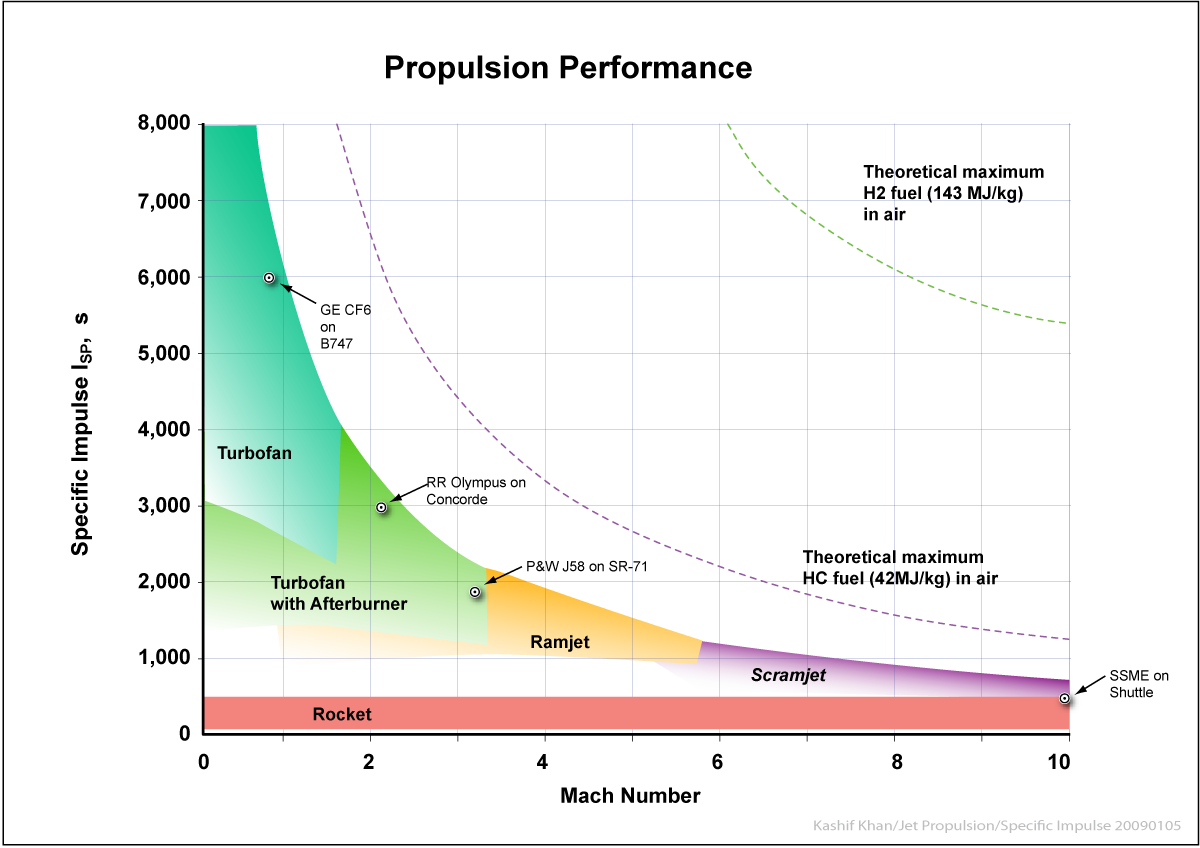
 Specific impulse as a function of speed for different jet types with kerosene fuel (hydrogen Isp would be about twice as high). Although efficiency plummets with speed, greater distances are covered, it turns out that efficiency per unit distance (per km or mile) is roughly independent of speed for jet engines as a group; however airframes become inefficient at supersonic speeds
Fuel/propellant consumption
A closely related (but different) concept to energy efficiency is the rate of consumption of propellant mass. Propellant consumption in jet engines is measured by Specific Fuel Consumption, Specific impulse or Effective exhaust velocity. They all measure the same thing. Specific impulse and effective exhaust velocity are strictly proportional, whereas specific fuel consumption is inversely proportional to the others.
For airbreathing engines such as turbojets energy efficiency and propellant (fuel) efficiency are much the same thing, since the propellant is a fuel and the source of energy. In rocketry, the propellant is also the exhaust, and this means that a high energy propellant gives better propellant efficiency but can in some cases actually can give lower energy efficiency.
Specific fuel consumption (SFC), specific impulse, and effective exhaust velocity numbers for various larger rocket engines. Engine type Scenario SFC in lb/(lbf·h) SFC in g/(kN·s) Specific impulse (s) Effective exhaust velocity (m/s) NK-33 rocket engine Vacuum 10.9 309 331[28] 3,240 SSME rocket engine Space shuttle vacuum 7.95 225 453[29] 4,423 Ramjet Mach 1 4.5 127 800 7,877 J-58 turbojet SR-71 at Mach 3.2 (Wet) 1.9 53.8 1,900 18,587 Rolls-Royce/Snecma Olympus 593 Concorde Mach 2 cruise (Dry) 1.195[30] 33.8 3,012 29,553 CF6-80C2B1F turbofan Boeing 747-400 cruise 0.605[30] 17.1 5,950 58,400 General Electric CF6 turbofan Sea level 0.307[30] 8.696 11,700 115,000 It can be seen that the subsonic turbofans such as General Electric's CF6 uses a lot less fuel to generate thrust for a second than Concorde's turbojet, the 593. However, since energy is force times distance and the distance per second is greater for Concorde, the actual power generated by the engine for the same amount of fuel is higher for Concorde at Mach 2 cruise than the CF6. The Concorde's engines are more efficient for thrust per mile, indeed, the most efficient ever.[31]
Thrust-to-weight ratio
Main article: Thrust-to-weight ratioThe thrust to weight ratio of jet engines of similar principles varies somewhat with scale, but mostly is a function of engine construction technology. Clearly for a given engine, the lighter the engine, the better the thrust to weight is, the less fuel is used to compensate for drag due to the lift needed to carry the engine weight, or to accelerate the mass of the engine.
As can be seen in the following table, rocket engines generally achieve very much higher thrust to weight ratios than duct engines such as turbojet and turbofan engines. This is primarily because rockets almost universally use dense liquid or solid reaction mass which gives a much smaller volume and hence the pressurisation system that supplies the nozzle is much smaller and lighter for the same performance. Duct engines have to deal with air which is 2-3 orders of magnitude less dense and this gives pressures over much larger areas, and which in turn results in more engineering materials being needed to hold the engine together and for the air compressor.
Jet or Rocket engine Mass, kg Jet or rocket thrust, kN Thrust-to-weight ratio RD-0410 nuclear rocket engine[32][33] 2000 35.2 1.8 J-58 (SR-71 Blackbird jet engine)[34][35] 2722 150 5.2 Concorde's Rolls-Royce/Snecma Olympus 593
turbojet with reheat[36][37]3175 169.2 5.4 RD-0750 rocket engine, three-propellant mode[38] 4621 1413 31.2 RD-0146 rocket engine[32] 260 98 38.5 Space Shuttle's SSME rocket engine[39] 3177 2278 73.2 RD-180 rocket engine[40] 5393 4152 78.6 F-1 (Saturn V first stage)[41] 8391 7740.5 94.1 NK-33 rocket engine[42] 1222 1638 136.8 Rocket thrusts are vacuum thrusts unless otherwise noted
Comparison of types
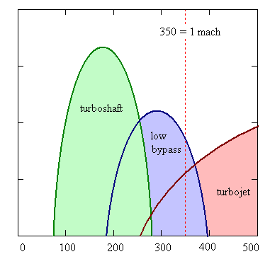
 Comparative suitability for (left to right) turboshaft, low bypass and turbojet to fly at 10 km altitude in various speeds. Horizontal axis - speed, m/s. Vertical axis displays engine efficiency.
Propeller engines are useful for comparison. They accelerate a large mass of air but by a relatively small maximum change in speed. This low speed limits the maximum thrust of any propeller driven airplane. However, because they accelerate a large mass of air, propeller engines, such as turboprops, can be very efficient.
On the other hand, turbojets accelerate a much smaller mass of the air and burned fuel, but they emit it at the much higher speeds possible with a de Laval nozzle. This is why they are suitable for supersonic and higher speeds.
Low bypass turbofans have the mixed exhaust of the two air flows, running at different speeds (c1 and c2). The thrust of such engine is
- S = m1 (c1 - v) + m2 (c2 - v)
where m1 and m2 are the air masses, being blown from the both exhausts. Such engines are effective at lower speeds, than the pure jets, but at higher speeds than the turboshafts and propellers in general. For instance, at the 10 km altitude, turboshafts are most effective at about Mach 0.4 (0.4 times the speed of sound), low bypass turbofans become more effective at about Mach 0.75 and turbojets become more effective than mixed exhaust engines when the speed approaches Mach 2-3.
Rocket engines have extremely high exhaust velocity and thus are best suited for high speeds (hypersonic) and great altitudes. At any given throttle, the thrust and efficiency of a rocket motor improves slightly with increasing altitude (because the back-pressure falls thus increasing net thrust at the nozzle exit plane), whereas with a turbojet (or turbofan) the falling density of the air entering the intake (and the hot gases leaving the nozzle) causes the net thrust to decrease with increasing altitude. Rocket engines are more efficient than even scramjets above roughly Mach 15.[43]
Altitude and speed
With the exception of scramjets, jet engines, deprived of their inlet systems can only accept air at around half the speed of sound. The inlet system's job for transonic and supersonic aircraft is to slow the air and perform some of the compression.
The limit on maximum altitude for engines is set by flammability- at very high altitudes the air becomes too thin to burn, or after compression, too hot. For turbojet engines altitudes of about 40 km appear to be possible, whereas for ramjet engines 55 km may be achievable. Scramjets may theoretically manage 75 km.[44] Rocket engines of course have no upper limit.
At more modest altitudes, flying faster compresses the air in at the front of the engine, and this greatly heats the air. The upper limit is usually thought to be about Mach 5-8, as above about Mach 5.5, the atmospheric nitrogen tends to react due to the high temperatures at the inlet and this consumes significant energy. The exception to this is scramjets which may be able to achieve about Mach 15 or more[citation needed], as they avoid slowing the air, and rockets again have no particular speed limit.
Noise
Noise is due to shockwaves that form when the exhaust jet interacts with the external air. The intensity of the noise is proportional to the thrust as well as proportional to the fourth power of the jet velocity.[citation needed] Generally then, the lower speed exhaust jets emitted from engines such as high bypass turbofans are the quietest, whereas the fastest jets, such as rockets and turbojets and ramjets are the loudest.
Although some variation in jet speed can often be arranged from a jet engine (such as by throttling back and adjusting the nozzle) it is difficult to vary the jet speed from an engine over a very wide range. Engines for supersonic vehicles such as Concorde, military jets and rockets need to have supersonic exhaust to support their top speeds, making them especially noisy even at low speed.
See also
- Air turboramjet
- Balancing machine
- Jet engine performance
- Jet aircraft
- Jetboat
- Variable Cycle Engine
- Pulse jet
- Turborocket
- Rocket turbine engine
- Rocket engine nozzles
- Spacecraft propulsion
- Water injection (engines)
- Turbojet development at the RAE
References
Notes
- ^ Encyclopædia Britannica. "Encyclopedia Britannica: Internal Combustion Engine". Britannica.com. http://www.britannica.com/EBchecked/topic/290504/internal-combustion-engine. Retrieved 2010-03-26.
- ^ a b "ch10-3". Hq.nasa.gov. http://www.hq.nasa.gov/pao/History/SP-468/ch10-3.htm. Retrieved 2010-03-26.
- ^ propeller efficiency[dead link]
- ^ Maxime Guillaume, "Propulseur par réaction sur l'air," French patent no. 534,801 (filed: 3 May 1921; issued: 13 January 1922). Available on-line (in French) at: http://v3.espacenet.com/origdoc?DB=EPODOC&IDX=FR534801&F=0&QPN=FR534801 .
- ^ "Chasing the Sun - Frank Whittle". PBS. http://www.pbs.org/kcet/chasingthesun/innovators/fwhittle.html. Retrieved 2010-03-26.
- ^ "History - Frank Whittle (1907 - 1996)". BBC. http://www.bbc.co.uk/history/historic_figures/whittle_frank.shtml. Retrieved 2010-03-26.
- ^ Frank Whittle, "Improvements relating to the propulsion of aircraft and other vehicles," British patent no. 347,206 (filed: 16 January 1930). Available on-line at: http://v3.espacenet.com/origdoc?DB=EPODOC&IDX=GB347206&F=0&QPN=GB347206 .
- ^ The History of the Jet Engine - Sir Frank Whittle - Hans Von Ohain Ohain said that he had not read Whittle's patent and Whittle believed him (Frank Whittle 1907-1996) however the Whittle patent was in German libraries and Whittle's son had suspicions that Ohain had read or heard of it (The History of the Jet Engine - Sir Frank Whittle a genius betrayed - )
- ^ Warsitz, Lutz: THE FIRST JET PILOT - The Story of German Test Pilot Erich Warsitz (p. 125), Pen and Sword Books Ltd., England, 2009
- ^ Mattingly, p. 6
- ^ Mattingly, pp. 6-8
- ^ Mattingly, pp. 9-11
- ^ a b Mattingly, p. 12
- ^ Hill & Peterson 1992, pp. 190.
- ^ Mattingly 2006, pp. 12-14.
- ^ Sweetman, Bill (2005). The Short, Happy Life of the Prop-fan. Air & Space Magazine. 1 September 2005.
- ^ a b Mattingly, p. 14
- ^ Flack, p. 16
- ^ Benson, Tom. Ramjet Propulsion. NASA Glenn Research Center. Updated: 11 July 2008. Retrieved: 23 July 2010.
- ^ Heiser and Pratt, pp. 23-4
- ^ X-51 Waverider makes historic hypersonic flight. United States Air Force. 26 May 2010. Retrieved: 23 July 2010.
- ^ "Rocket Thrust Equation". Grc.nasa.gov. 2008-07-11. http://www.grc.nasa.gov/WWW/K-12/airplane/rockth.html. Retrieved 2010-03-26.
- ^ GFC Rogers, and Cohen, H. Gas Turbine Theory, p.108 (5th Edition), HIH Saravanamuttoo
- ^ Rocket propulsion elements, Sutton, Biblarz- table 3-1
- ^ In Newtonian mechanics kinetic energy is frame dependent. The kinetic energy is easiest to calculate when the speed is measured in the center of mass frame of the vehicle and (less obviously) its reaction mass/air i.e. the stationary frame before takeoff begins.
- ^ K.Honicke, R.Lindner, P.Anders, M.Krahl, H.Hadrich, K.Rohricht. Beschreibung der Konstruktion der Triebwerksanlagen. Interflug, Berlin, 1968
- ^ Rocket Propulsion elements- seventh edition, pg 37-38
- ^ Astronautix NK33
- ^ Astronautix SSME
- ^ a b c "Data on Large Turbofan Engines". Aircraft Aerodynamics and Design Group. Stanford University. http://adg.stanford.edu/aa241/propulsion/largefan.html. Retrieved 22 December 2009.
- ^ "NOVA transcript". Pbs.org. http://www.pbs.org/wgbh/nova/transcripts/3203_concorde.html. Retrieved 2010-03-26.
- ^ a b Wade, Mark. "RD-0410". Encyclopedia Astronautica. http://www.astronautix.com/engines/rd0410.htm. Retrieved 2009-09-25.
- ^ "«Konstruktorskoe Buro Khimavtomatiky» - Scientific-Research Complex / RD0410. Nuclear Rocket Engine. Advanced launch vehicles". KBKhA - Chemical Automatics Design Bureau. http://www.kbkha.ru/?p=8&cat=11&prod=66. Retrieved 2009-09-25.
- ^ Aircraft: Lockheed SR-71A Blackbird
- ^ "Factsheets : Pratt & Whitney J58 Turbojet". National Museum of the United States Air Force. http://www.nationalmuseum.af.mil/factsheets/factsheet.asp?id=880. Retrieved 2010-04-15.
- ^ "ROLLS-ROYCE SNECMA OLYMPUS - Jane's Transport News". http://www.janes.com/transport/news/jae/jae000725_1_n.shtml. Retrieved 2009-09-25. "With afterburner, reverser and nozzle ... 3,175 kg ... Afterburner ... 169.2 kN"
- ^ [1]
- ^ "«Konstruktorskoe Buro Khimavtomatiky» - Scientific-Research Complex / RD0750.". KBKhA - Chemical Automatics Design Bureau. http://www.kbkha.ru/?p=8&cat=11&prod=57. Retrieved 2009-09-25.
- ^ SSME
- ^ "RD-180". http://www.astronautix.com/engines/rd180.htm. Retrieved 2009-09-25.
- ^ http://www.astronautix.com/engines/f1.htm
- ^ Astronautix NK-33 entry
- ^ "Microsoft PowerPoint - KTHhigspeed08.ppt" (PDF). http://www.energy.kth.se/courses/4A1346/2ndLecture/KTH%20High%20Speed.pdf. Retrieved 2010-03-26.
- ^ "Scramjet". Orbitalvector.com. 2002-07-30. http://www.orbitalvector.com/Orbital%20Travel/Scramjets/Scramjets.htm. Retrieved 2010-03-26.
Bibliography
- Brooks, David S. (1997). Vikings at Waterloo: Wartime Work on the Whittle Jet Engine by the Rover Company. Rolls-Royce Heritage Trust. ISBN 1872922082.
- Flack, Ronald D. (2005). Fundamentals of Jet Propulsion with Applications. Cambridge Aerospace Series. New York, NY: Cambridge University Press. ISBN 9780521819831.
- Golley, John (1997). Genesis of the Jet: Frank Whittle and the Invention of the Jet Engine. Crowood Press. ISBN 185310860X.
- Heiser, William H.; Pratt, David T. (1994). Hypersonic Airbreathing Propulsion. AIAA Education Series. Washington, DC: American Institute of Aeronautics and Astronautics. ISBN 1563470357.
- Hill, Philip; Peterson, Carl (1992), Mechanics and Thermodynamics of Propulsion (2nd ed.), New York: Addison-Wesley, ISBN 0-201-14659-2
- Kerrebrock, Jack L. (1992). Aircraft Engines and Gas Turbines (2nd ed.). Cambridge, MA: The MIT Press. ISBN 9780262111621.
- Mattingly, Jack D. (2006). Elements of Propulsion: Gas Turbines and Rockets. AIAA Education Series. Reston, VA: American Institute of Aeronautics and Astronautics. ISBN 1563477793.
- Warsitz, Lutz; Brooks, Geoffrey (2009). The First Jet Pilot - The Story of German Test Pilot Erich Warsitz. England: Pen and Sword Books Ltd.. ISBN 9781844158188.
External links
- A New “Open Rotor” Jet Engine That Could Reduce Fuel Consumption
- Technology Speed of Civil Jet Engines
- Animated Jet Engines to understand how it works
- RMCybernetics - A simple Homemade Jet Engine
- Journey through a jet engine(flash)
- How Stuff Works article on how a Gas Turbine Engine works
- Influence of the Jet Engine on the Aerospace Industry
- An Overview of Military Jet Engine History (Rand Corp., 24 pgs, PDF)
- A jet propulsion bicycle
- Basic jet engine tutorial (Quicktime Video
- Jet powered model of an Airbus A330 at 1/16 scale
- Pulsejet in aeromodelling (French)
- Interactive jet engine simulator for learning
- The official Erich Warsitz website–the world’s first jet pilot
Heat engines Carnot engine · Fluidyne · Gas turbine · Hot air · Jet · Photo-Carnot engine · Piston · Pistonless (Rotary) · Rijke tube · Rocket · Split-single · Steam (reciprocating) · Steam turbine · Stirling · ThermoacousticThermodynamic cycle Categories:- Energy conversion
- Gas turbines
- Jet engines
- Compressors
- Turbomachinery
- Thermodynamics
- Fluid dynamics
- Aerodynamics
- English inventions


Wikimedia Foundation. 2010.