- Dye-sensitized solar cell
-
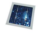
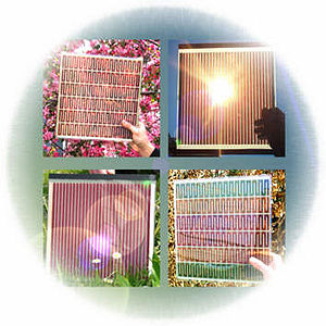 A selection of dye-sensitized solar cells
A dye-sensitized solar cell (DSSC, DSC or DYSC[1]) is a low-cost solar cell belonging to the group of thin film solar cells.[2] It is based on a semiconductor formed between a photo-sensitized anode and an electrolyte, a photoelectrochemical system. A later version of a dye solar cell, also known as the Grätzel cell, was invented by Michael Grätzel and Brian O'Regan at the École Polytechnique Fédérale de Lausanne in 1991.[3] Michael Grätzel won the 2010 Millennium Technology Prize for its invention.[4]
Because it could potentially be made of low-cost materials, if the use of noble materials like Platinum and Ruthenium is limited, and does not require elaborate apparatus to manufacture, this cell is technically attractive. Likewise, manufacture can be significantly less expensive than older solid-state cell designs. It can also be engineered into flexible sheets and is mechanically robust, requiring no protection from minor events like hail or tree strikes. Although its conversion efficiency is less than the best thin-film cells, in theory its price/performance ratio (kWh/(m2·annum·dollar)) should be high enough to allow them to compete with fossil fuel electrical generation by achieving grid parity. Commercial applications, which were held up due to chemical stability problems,[5] are now forecast in the European Union Photovoltaic Roadmap to significantly contribute to renewable electricity generation by 2020.
Contents
Current technology: semiconductor solar cells
In a traditional solid-state semiconductor, a solar cell is made from two doped crystals, one doped with n-type impurities (n-type semiconductor), which add additional free conduction band electrons, and the other doped with p-type impurities (p-type semiconductor), which add additional electron holes. When placed in contact, some of the electrons in the n-type portion flow into the p-type to "fill in" the missing electrons, also known as electron holes. Eventually enough electrons will flow across the boundary to equalize the Fermi levels of the two materials. The result is a region at the interface, the p-n junction, where charge carriers are depleted and/or accumulated on each side of the interface. In silicon, this transfer of electrons produces a potential barrier of about 0.6 to 0.7 V.[6]
When placed in the sun, photons of the sunlight can excite electrons on the p-type side of the semiconductor, a process known as photoexcitation. In silicon, sunlight can provide enough energy to push an electron out of the lower-energy valence band into the higher-energy conduction band. As the name implies, electrons in the conduction band are free to move about the silicon. When a load is placed across the cell as a whole, these electrons will flow out of the p-type side into the n-type side, lose energy while moving through the external circuit, and then back into the p-type material where they can once again re-combine with the valence-band hole they left behind. In this way, sunlight creates an electrical current.[6]
In any semiconductor, the band gap means that only photons with that amount of energy, or more, will contribute to producing a current. In the case of silicon, the majority of visible light from red to violet has sufficient energy to make this happen. Unfortunately higher energy photons, those at the blue and violet end of the spectrum, have more than enough energy to cross the band gap; although some of this extra energy is transferred into the electrons, the majority of it is wasted as heat. Another issue is that in order to have a reasonable chance of capturing a photon, the n-type layer has to be fairly thick. This also increases the chance that a freshly ejected electron will meet up with a previously created hole in the material before reaching the p-n junction. These effects produce an upper limit on the efficiency of silicon solar cells, currently around 12 to 15% for common modules and up to 25% for the best laboratory cells (about 30% is the theoretical maximum efficiency for single band gap solar cells, see Shockley-Queisser limit.).
By far the biggest problem with the conventional approach is cost; solar cells require a relatively thick layer of doped silicon in order to have reasonable photon capture rates, and silicon processing is expensive. There have been a number of different approaches to reduce this cost over the last decade, notably the thin-film approaches, but to date they have seen limited application due to a variety of practical problems. Another line of research has been to dramatically improve efficiency through the multi-junction approach, although these cells are very high cost and suitable only for large commercial deployments. In general terms the types of cells suitable for rooftop deployment have not changed significantly in efficiency, although costs have dropped somewhat due to increased supply.
Dye-sensitized solar cells
In the late 1960s it was discovered that illuminated organic dyes can generate electricity at oxide electrodes in electrochemical cells [7]. In an effort to understand and simulate the primary processes in photosynthesis the phenomenon was studied at the University of Berkeley with chlorophyll extracted from spinach (bio-mimetic or bionic approach) [8]. On the basis of such experiments electric power generation via the dye sensitization solar cell (DSSC) principle was demonstrated and discussed in 1972 [9]. The instability of the dye solar cell was identified as a main challenge. Its efficiency could, during the following two decades, be improved by optimizing the porosity of the electrode prepared from fine oxide powder, but the instability remained a problem [10]. A modern DSSC, the Graetzel cell, is composed of a porous layer of titanium dioxide nanoparticles, covered with a molecular dye that absorbs sunlight, like the chlorophyll in green leaves. The titanium dioxide is immersed under an electrolyte solution, above which is a platinum-based catalyst. As in a conventional alkaline battery, an anode (the titanium dioxide) and a cathode (the platinum) are placed on either side of a liquid conductor (the electrolyte).
Sunlight passes through the transparent electrode into the dye layer where it can excite electrons that then flow into the titanium dioxide. The electrons flow toward the transparent electrode where they are collected for powering a load. After flowing through the external circuit, they are re-introduced into the cell on a metal electrode on the back, flowing into the electrolyte. The electrolyte then transports the electrons back to the dye molecules.
Dye-sensitized solar cells separate the two functions provided by silicon in a traditional cell design. Normally the silicon acts as both the source of photoelectrons, as well as providing the electric field to separate the charges and create a current. In the dye-sensitized solar cell, the bulk of the semiconductor is used solely for charge transport, the photoelectrons are provided from a separate photosensitive dye. Charge separation occurs at the surfaces between the dye, semiconductor and electrolyte.
The dye molecules are quite small (nanometer sized), so in order to capture a reasonable amount of the incoming light the layer of dye molecules needs to be made fairly thick, much thicker than the molecules themselves. To address this problem, a nanomaterial is used as a scaffold to hold large numbers of the dye molecules in a 3-D matrix, increasing the number of molecules for any given surface area of cell. In existing designs, this scaffolding is provided by the semiconductor material, which serves double-duty.
Construction
In the case of the original Grätzel and O'Regan design, the cell has 3 primary parts. On top is a transparent anode made of fluoride-doped tin dioxide (SnO2:F) deposited on the back of a (typically glass) plate. On the back of this conductive plate is a thin layer of titanium dioxide (TiO2), which forms into a highly porous structure with an extremely high surface area. TiO2 only absorbs a small fraction of the solar photons (those in the UV).[11] The plate is then immersed in a mixture of a photosensitive ruthenium-polypyridine dye (also called molecular sensitizers[11]) and a solvent. After soaking the film in the dye solution, a thin layer of the dye is left covalently bonded to the surface of the TiO2.
A separate plate is then made with a thin layer of the iodide electrolyte spread over a conductive sheet, typically platinum metal. The two plates are then joined and sealed together to prevent the electrolyte from leaking. The construction is simple enough that there are hobby kits available to hand-construct them.[12] Although they use a number of "advanced" materials, these are inexpensive compared to the silicon needed for normal cells because they require no expensive manufacturing steps. TiO2, for instance, is already widely used as a paint base.
Operation
Sunlight enters the cell through the transparent SnO2:F top contact, striking the dye on the surface of the TiO2. Photons striking the dye with enough energy to be absorbed create an excited state of the dye, from which an electron can be "injected" directly into the conduction band of the TiO2. From there it moves by diffusion (as a result of an electron concentration gradient) to the clear anode on top.
Meanwhile, the dye molecule has lost an electron and the molecule will decompose if another electron is not provided. The dye strips one from iodide in electrolyte below the TiO2, oxidizing it into triiodide. This reaction occurs quite quickly compared to the time that it takes for the injected electron to recombine with the oxidized dye molecule, preventing this recombination reaction that would effectively short-circuit the solar cell.
The triiodide then recovers its missing electron by mechanically diffusing to the bottom of the cell, where the counter electrode re-introduces the electrons after flowing through the external circuit.
Efficiency
Main article: Solar conversion efficiencySeveral important measures are used to characterize solar cells. The most obvious is the total amount of electrical power produced for a given amount of solar power shining on the cell. Expressed as a percentage, this is known as the solar conversion efficiency. Electrical power is the product of current and voltage, so the maximum values for these measurements are important as well, Jsc and Voc respectively. Finally, in order to understand the underlying physics, the "quantum efficiency" is used to compare the chance that one photon (of a particular energy) will create one electron.
In quantum efficiency terms, DSSCs are extremely efficient. Due to their "depth" in the nanostructure there is a very high chance that a photon will be absorbed, and the dyes are very effective at converting them to electrons. Most of the small losses that do exist in DSSC's are due to conduction losses in the TiO2 and the clear electrode, or optical losses in the front electrode. The overall quantum efficiency for green light is about 90%, with the "lost" 10% being largely accounted for by the optical losses in top electrode. The quantum efficiency of traditional designs vary, depending on their thickness, but are about the same as the DSSC.
In theory, the maximum voltage generated by such a cell is simply the difference between the (quasi-)Fermi level of the TiO2 and the redox potential of the electrolyte, about 0.7 V under solar illumination conditions (Voc). That is, if an illuminated DSSC is connected to a voltmeter in an "open circuit", it would read about 0.7 V. In terms of voltage, DSSCs offer slightly higher Voc than silicon, about 0.7 V compared to 0.6 V. This is a fairly small difference, so real-world differences are dominated by current production, Jsc.
Although the dye is highly efficient at converting absorbed photons into free electrons in the TiO2, only photons absorbed by the dye ultimately produce current. The rate of photon absorption depends upon the absorption spectrum of the sensitized TiO2 layer and upon the solar flux spectrum. The overlap between these two spectra determines the maximum possible photocurrent. Typically used dye molecules generally have poorer absorption in the red part of the spectrum compared to silicon, which means that fewer of the photons in sunlight are usable for current generation. These factors limit the current generated by a DSSC, for comparison, a traditional silicon-based solar cell offers about 35 mA/cm2, whereas current DSSCs offer about 20 mA/cm2.
Overall peak power production efficiency for current DSSCs is about 11%.[13][14]
Degradation
DSSCs degrade when exposed to ultraviolet radiation. The barrier layer may include UV stabilizers and/or UV absorbing luminescent chromophores (which emit at longer wavelengths) and antioxidants to protect and improve the efficiency of the cell.[15]
Advantages
DSSCs are currently the most efficient third-generation[16] (2005 Basic Research Solar Energy Utilization 16) solar technology available. Other thin-film technologies are typically between 5% and 13%, and traditional low-cost commercial silicon panels operate between 12% and 15%. This makes DSSCs attractive as a replacement for existing technologies in "low density" applications like rooftop solar collectors, where the mechanical robustness and light weight of the glass-less collector is a major advantage. They may not be as attractive for large-scale deployments where higher-cost higher-efficiency cells are more viable, but even small increases in the DSSC conversion efficiency might make them suitable for some of these roles as well.
There is another area where DSSCs are particularly attractive. The process of injecting an electron directly into the TiO2 is qualitatively different to that occurring in a traditional cell, where the electron is "promoted" within the original crystal. In theory, given low rates of production, the high-energy electron in the silicon could re-combine with its own hole, giving off a photon (or other form of energy) and resulting in no current being generated. Although this particular case may not be common, it is fairly easy for an electron generated in another molecule to hit a hole left behind in a previous photoexcitation.
In comparison, the injection process used in the DSSC does not introduce a hole in the TiO2, only an extra electron. Although it is energetically possible for the electron to recombine back into the dye, the rate at which this occurs is quite slow compared to the rate that the dye regains an electron from the surrounding electrolyte. Recombination directly from the TiO2 to species in the electrolyte is also possible although, again, for optimized devices this reaction is rather slow.[17] On the contrary, electron transfer from the platinum coated electrode to species in the electrolyte is necessarily very fast.
As a result of these favorable "differential kinetics", DSSCs work even in low-light conditions. DSSCs are therefore able to work under cloudy skies and non-direct sunlight, whereas traditional designs would suffer a "cutout" at some lower limit of illumination, when charge carrier mobility is low and recombination becomes a major issue. The cutoff is so low they are even being proposed for indoor use, collecting energy for small devices from the lights in the house.[18]
A practical advantage, one DSSCs share with most thin-film technologies, is that the cell's mechanical robustness indirectly leads to higher efficiencies in higher temperatures. In any semiconductor, increasing temperature will promote some electrons into the conduction band "mechanically". The fragility of traditional silicon cells requires them to be protected from the elements, typically by encasing them in a glass box similar to a greenhouse, with a metal backing for strength. Such systems suffer noticeable decreases in efficiency as the cells heat up internally. DSSCs are normally built with only a thin layer of conductive plastic on the front layer, allowing them to radiate away heat much easier, and therefore operate at lower internal temperatures.
Disadavantages
The major disadvantage to the DSSC design is the use of the liquid electrolyte, which has temperature stability problems. At low temperatures the electrolyte can freeze, ending power production and potentially leading to physical damage. Higher temperatures cause the liquid to expand, making sealing the panels a serious problem. The fact, that costly Ruthenium (dye), Platinum (catalyst) and conducting glass or plastic (contact) is needed in the Graetzel cell, has to be considered in cost projections. Another major drawback is the electrolyte solution, which contains volatile organic solvents and must be carefully sealed. This, along with the fact that the solvents permeate plastics, has precluded large-scale outdoor application and integration into flexible structure.[19]
Replacing the liquid electrolyte with a solid has been a major ongoing field of research. Recent experiments using solidified melted salts have shown some promise, but currently suffer from higher degradation during continued operation, and are not flexible.[20]
Photocathodes and tandem cells
Grätzel’s cell operates as a photoanode (n-DSC), where photocurrent result from electron injection by the sensitized dye. Photocathodes (p-DSCs) operate in an inverse mode compared to the conventional n-DSC, where dye-excitation is followed by rapid electron transfer from a p-type semiconductor to the dye (dye-sensitized hole injection, instead of electron injection). Such p-DSCs and n-DSCs can be combined to construct tandem solar cells (pn-DSCs) and the theoretical efficiency of tandem DSCs is well beyond that of single-junction DSCs.
A standard tandem cell consists of one n-DSC and one p-DSC in a simple sandwich configuration with an intermediate electrolyte layer. n-DSC and p-DSC are connected in series, which implies that the resulting photocurrent will be controlled by the weakest photoelectrode, whereas photovoltages are additive. Thus, photocurrent matching is very important for the construction of highly efficient tandem pn-DSCs. However, unlike n-DSCs, fast charge recombination following dye-sensitized hole injection usually resulted in low photocurrents in p-DSC and thus hampered the efficiency of the overall device.
Researchers have found that using dyes comprising a perylenemonoimid (PMI) as the acceptor and an oligothiophene coupled to triphenylamine as the donor greatly improve the performance of p-DSC by reducing charge recombination rate following dye-sensitized hole injection. The researchers constructed a tandem DSC device with NiO on the p-DSC side and TiO2 on the n-DSC side. Photocurrent matching was achieved through adjustment of NiO and TiO2 film thicknesses to control the optical absorptions and therefore match the photocurrents of both electrodes. The energy conversion efficiency of the device is 1.91%, which exceeds the efficiency of its individual components, but is still much lower than that of high performance n-DSC devices (6%–11%). The results are still promising since the tandem DSC was in itself rudimentary. The dramatic improvement in performance in p-DSC can eventually lead to tandem devices with much greater efficiency than lone n-DSCs.[21]
Development
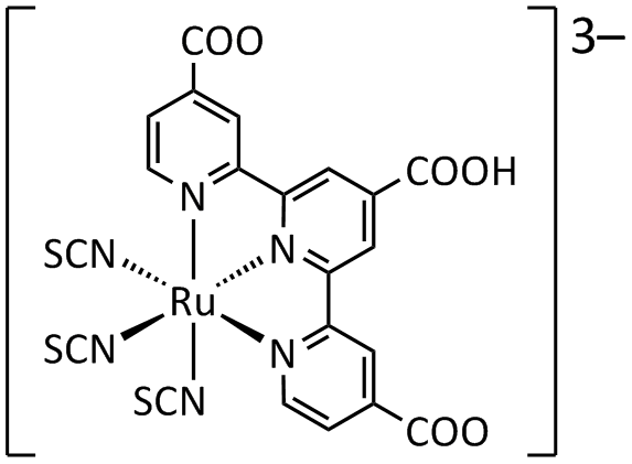
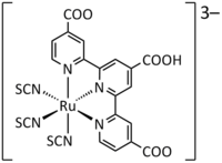 "Black Dye", an anionic Ru-terpyridine complex
The dyes used in early experimental cells (circa 1995) were sensitive only in the high-frequency end of the solar spectrum, in the UV and blue. Newer versions were quickly introduced (circa 1999) that had much wider frequency response, notably "triscarboxy-ruthenium terpyridine" [Ru(4,4',4"-(COOH)3-terpy)(NCS)3], which is efficient right into the low-frequency range of red and IR light. The wide spectral response results in the dye having a deep brown-black color, and is referred to simply as "black dye".[22] The dyes have an excellent chance of converting a photon into an electron, originally around 80% but improving to almost perfect conversion in more recent dyes, the overall efficiency is about 90%, with the "lost" 10% being largely accounted for by the optical losses in top electrode.
A solar cell must be capable of producing electricity for at least twenty years, without a significant decrease in efficiency (life span). The "black dye" system was subjected to 50 million cycles, the equivalent of ten years' exposure to the sun in Switzerland. No discernible performance decrease was observed. However the dye is subject to breakdown in high-light situations. Over the last decade an extensive research program has been carried out to address these concerns. The newer dyes included 1-ethyl-3 methylimidazolium tetrocyanoborate [EMIB(CN)4] which is extremely light- and temperature-stable, copper-diselenium [Cu(In,GA)Se2] which offers higher conversion efficiencies, and others with varying special-purpose properties.
DSSCs are still at the start of their development cycle. Efficiency gains are possible and have recently started more widespread study. These include the use of quantum dots for conversion of higher-energy (higher frequency) light into multiple electrons, using solid-state electrolytes for better temperature response, and changing the doping of the TiO2 to better match it with the electrolyte being used.
New developments
2003
A group of researchers at the Swiss Federal Institute of Technology has reportedly increased the thermostability of DSC by using amphiphilic ruthenium sensitizer in conjunction with quasi-solid-state gel electrolyte. The stability of the device matches that of a conventional inorganic silicon based solar cell. The cell sustained heating for 1,000 h at 80 °C.
The group has previously prepared an ruthenium amphiphilic dye Z-907 (cis-Ru(H2dcbpy)(dnbpy)(NCS)2,where the ligand H2dcbpy is 4,4′-dicarboxylic acid-2,2′-bipyridine and dnbpy is 4,4′-dinonyl-2,2′-bipyridine) to increase dye tolerance to water in the electrolytes. In addition, the group also prepared a quasi-solid-state gel electrolye with a 3-methoxypropionitrile (MPN)-based liquid electrolyte that was solidified by a photochemically stable fluorine polymer, poly(vinylidenefluoride-co-hexafluoropropylene (PVDF-HFP).
The use of the amphiphilic Z-907 dye in conjunction with the polymer gel electrolyte in DSC achieved an energy conversion efficiency of 6.1%. More importantly, the device was stable under thermal stress and soaking with light. The high conversion efficiency of the cell was sustained after heating for 1,000 h at 80 °C, maintaining 94% of its initial value. After accelerated testing in a solar simulator for 1,000 h of light-soaking at 55 °C (100 mW cm−2) the efficiency had decreased by less than 5% for cells covered with an ultraviolet absorbing polymer film. These results are well within the limit for that of traditional inorganic silicon solar cells.
The enhanced performance may arise from a decrease in solvent permeation across the sealant due to the application of the polymer gel electrolyte. The polymer gel electrolyte is quasi-solid at room temperature, and becomes a viscous liquid (viscosity: 4.34 mPa·s) at 80 °C compared with the traditional liquid electrolyte (viscosity: 0.91 mPa·s). The much improved stabilities of the device under both thermal stress and soaking with light has never before been seen in DSCs, and they match the durability criteria applied to solar cells for outdoor use, which makes these devices viable for practical application.[23][24]
2006
The first successful solid-hybrid dye-sensitized solar cells were reported.[20]
To improve electron transport in these solar cells, while maintaining the high surface area needed for dye adsorption, two researchers have designed alternate semiconductor morphologies, such as arrays of nanowires and a combination of nanowires and nanoparticles, to provide a direct path to the electrode via the semiconductor conduction band. Such structures may provide a means to improve the quantum efficiency of DSSCs in the red region of the spectrum, where their performance is currently limited.[25]
On August 2006, to prove the chemical and thermal robustness of the 1-ethyl-3 methylimidazolium tetracyanoborate solar cell, the researchers subjected the devices to heating at 80 °C in the dark for 1000 hours, followed by light soaking at 60 °C for 1000 hours. After dark heating and light soaking, 90% of the initial photovoltaic efficiency was maintained – the first time such excellent thermal stability has been observed for a liquid electrolyte that exhibits such a high conversion efficiency. Contrary to silicon solar cells, whose performance declines with increasing temperature, the dye-sensitized solar-cell devices were only negligibly influenced when increasing the operating temperature from ambient to 60 °C.
April 2007
Wayne Campbell at Massey University, New Zealand, has experimented with a wide variety of organic dyes based on porphyrin.[26] In nature, porphyrin is the basic building block of the hemoproteins, which include chlorophyll in plants and hemoglobin in animals. He reports efficiency on the order of 5.6% using these low-cost dyes.[27]
June 2008
An article published in Nature Materials demonstrated cell efficiencies of 8.2% using a new solvent-free liquid redox electrolyte consisting of a melt of three salts, as an alternative to using organic solvents as an electrolyte solution. Although the efficiency with this electrolyte is less than the 11% being delivered using the existing iodine-based solutions, the team is confident the efficiency can be improved.[28]
2009
A group of researchers at Georgia Tech made dye-sensitized solar cells with a higher effective surface area by wrapping the cells around a quartz optical fiber.[29][30] The researchers removed the cladding from optical fibers, grew zinc oxide nanowires along the surface, treated them with dye molecules, surrounded the fibers by an electrolyte and a metal film that carries electrons off the fiber. The cells are six times more efficient than a zinc oxide cell with the same surface area.[29] Photons bounce inside the fiber as they travel, so there are more chances to interact with the solar cell and produce more current. These devices only collect light at the tips, but future fiber cells could be made to absorb light along the entire length of the fiber, which would require a coating that is conductive as well as transparent.[29] Max Shtein of the University of Michigan said a sun-tracking system would not be necessary for such cells, and would work on cloudy days when light is diffuse.[29]
2010
Researchers at the École Polytechnique Fédérale de Lausanne and at the Université du Québec à Montréal claim to have overcome two of the DSC's major issues:[31]
- "new molecules" have been created for the electrolyte, resulting in a liquid or gel that is transparent and non-corrosive, which can increase the photovoltage and improve the cell's output and stability.
- At the cathode, platinum was replaced by cobalt sulfide, which is far less expensive, more efficient, more stable and easier to produce in the laboratory.[32]
2011
Dyesol and Tata steel announced in June the development of the world´s largest dye sensitized photovoltaic module, printed onto steel in a continuous line. [33]
Market introduction
Several commercial providers are promising availability of DSCs in the near future:[34]
- Dyesol officially opened its new manufacturing facilities in Queanbeyan on the 7th of October 2008. It has subsequently announced partnerships with Tata Steel and Pilkington Glass for the development and large scale manufacture of DSC BIPV. Dyesol has also entered working relationships with Merck, Umicore, CSIRO, Japanese Ministry of Economy and Trade, Singapore Aerospace Manufacturing and TIMO Korea[35][36]
- Solaronix, a Swiss company specialized in the production of DSC materials since 1993, has extended their premises in 2010 to host a manufacturing pilot line of DSC modules.[37]
- SolarPrint founded in 2008 by Dr. Mazhar Bari, Andre Fernon and Roy Horgan. SolarPrint is the first Ireland-based commercial entity involved in the manufacturing of PV technology. SolarPrint's innovation is the solution to the solvent based electrolyte which to date has prohibited the mass commercialisation of DSSC.
- G24innovations, founded in 2006, based in Cardiff, South Wales, UK. On October 17, 2007, claimed the production of the first commercial grade dye sensitised thin films.[38][39]
- Hydrogen Solar is another company making dye-sensitized cells.[40]
- Konarka, announced in 2002 that they were granted licensee rights to dye-sensitized solar cell technology from the Swiss Federal Institute of Technology (EPFL).
- Aisin Seiki has worked with Toyota Central R&D Labs to develop dye-sensitized solar cells (DSC) for applications in cars and homes.[41]
- Sony Corporation has developed dye-sensitized solar cells with an energy conversion efficiency of 10%, a level seen as necessary for commercial use. Sony has been supplied materials by Australia´s Dyesol[42][43]
See also
- Absorption
- Bronsted
- Chromophore
- Low-cost solar cell
- Luminescent solar concentrator
- Elution
- Organic photovoltaics
- Photoelectrochemical cell
- Solid-state solar cell
- Stationary phase
- Titanium dioxide
References
- ^ Haiying Wan, "Dye Sensitized Solar Cells", University of Alabama Department of Chemistry, p. 3
- ^ "Dye-Sensitized vs. Thin Film Solar Cells", European Institute for Energy Research, 30 June 2006
- ^ Brian O'Regan, Michael Grätzel (24 October 1991). "A low-cost, high-efficiency solar cell based on dye-sensitized colloidal TiO2 films". Nature 353 (6346): 737–740. Bibcode 1991Natur.353..737O. doi:10.1038/353737a0.
- ^ Professor Grätzel wins the 2010 millennium technology grand prize for dye-sensitized solar cells, 14.6.2010
- ^ Tributsch, H (2004). "Dye sensitization solar cells: a critical assessment of the learning curve". Coordination Chemistry Reviews 248 (13–14): 1511. doi:10.1016/j.ccr.2004.05.030.
- ^ a b "Photovoltaic Cells (Solar Cells), How They Work". specmat.com. http://www.specmat.com/Overview%20of%20Solar%20Cells.htm. Retrieved 2007-05-22.
- ^ Gerischer,H.; Michel-Beyerle,M.; Rebentrost, E.; Tributsch, H. (1968). "Sensitization of Charge-Injection into Semiconductors with Large Band Gap". Electrochim.Acta (13): 1509–1515.
- ^ Tributsch, H.; Calvin, M. (1971). "Electrochemistry of Excited Molecules: Photoelectrochemical Reactions of Chlorophylls". Photochem. Photobiol. (14): 95–112.
- ^ Tributsch, H. (1972). "Reaction of Excited Chorophyll Molecules at Electrodes and in Photosynthesis". Photochem.Photobiol. (16): 261–269.
- ^ Matsumura, M.; Matsudaira, S.; Tsubomura, H.; Takata, M.; Yanagida, H. (1980). "Dye Sensitization and Surface Structures of Semiconductor Electrodes". Ind. Eng. Chem. Prod. Res. Dev. (19(3)): 415–421.
- ^ a b Juan Bisquert, "Dye-sensitized solar cells", Departament de Física, Universitat Jaume I
- ^ "Dye Solar Cell Assembly Instructions". Solaronix. http://www.solaronix.com/technology/assembly/. Retrieved 2007-05-22.
- ^ American Chemical Society, "Ultrathin, Dye-sensitized Solar Cells Called Most Efficient To Date", ScienceDaily, 20 September 2006
- ^ Gao, F; Wang, Y; Zhang, J; Shi, D; Wang, M; Humphry-Baker, R; Wang, P; Zakeeruddin, Sm; Grätzel, M (2008). "A new heteroleptic ruthenium sensitizer enhances the absorptivity of mesoporous titania film for a high efficiency dye-sensitized solar cell.". Chemical communications (23): 2635–7. doi:10.1039/b802909a. PMID 18535691.
- ^ "Photovoltaic cell, European patent WO/2004/006292". http://www.wipo.int/pctdb/en/wo.jsp?IA=US2002018922&DISPLAY=DESC. Retrieved 2009-08-01.
- ^ Basic Research Needs for Solar Energy Utilization, U.S. Department of Energy Office of Basic Energy Sciences, 2005.
- ^ Jessica Krüger, "Interface engineering in solid-state dye sensitized solar cells", École Polytechnique Fédérale de Lausanne, 2003
- ^ Kimberly Patch, "Solar cell doubles as battery", Technology Research News, 2006
- ^ Ecole Polytechnique Fédérale de Lausanne, "New Efficiency Benchmark For Dye-sensitized Solar Cells", ScienceDaily, 3 November 2008
- ^ a b Nathalie Rossier-Iten, "Solid hybrid dye-sensitized solar cells: new organic materials, charge recombination and stability", École Polytechnique Fédérale de Lausanne, 2006
- ^ Nattestad, A; Mozer, AJ; Fischer, MK; Cheng, YB; Mishra, A; Bäuerle, P; Bach, U (2010). "Highly efficient photocathodes for dye-sensitized tandem solar cells.". Nature materials 9 (1): 31–5. Bibcode 2010NatMa...9...31N. doi:10.1038/nmat2588. PMID 19946281.
- ^ "Dye Sensitized Solar Cells (DYSC) based on Nanocrystalline Oxide Semiconductor Films". Laboratory for Photonics and Interfaces, École Polytechnique Fédérale de Lausanne. 2 February 1999. http://lpi.epfl.ch/solarcellE.html. Retrieved 2007-05-22.
- ^ Wang, Peng; Zakeeruddin, Shaik M.; Moser, Jacques E.; Nazeeruddin, Mohammad K.; Sekiguchi, Takashi; Grätzel, Michael (2003). "A stable quasi-solid-state dye-sensitized solar cell with an amphiphilic ruthenium sensitizer and polymer gel electrolyte". Nature Materials 2 (6): 402–7. Bibcode 2003NatMa...2..402W. doi:10.1038/nmat904. PMID 12754500.
- ^ Gratzel, M (2003). "Dye-sensitized solar cells". Journal of Photochemistry and Photobiology C: Photochemistry Reviews 4 (2): 145. doi:10.1016/S1389-5567(03)00026-1. http://photochemistry.epfl.ch/EDEY/DSC_review.pdf.
- ^ Michael Berger, "Nanowires Could Lead to Improved Solar Cells ", NewswireToday, 03/06/2006
- ^ "Taking nature’s cue for cheaper solar power"[dead link]
- ^ Wang, Q; Campbell, Wm; Bonfantani, Ee; Jolley, Kw; Officer, Dl; Walsh, Pj; Gordon, K; Humphry-Baker, R; Nazeeruddin, Mk; Grätzel, M (2005). "Efficient light harvesting by using green Zn-porphyrin-sensitized nanocrystalline TiO2 films.". The journal of physical chemistry. B 109 (32): 15397–409. doi:10.1021/jp052877w. PMID 16852953.
- ^ Bai, Yu; Cao, Yiming; Zhang, Jing; Wang, Mingkui; Li, Renzhi; Wang, Peng; Zakeeruddin, Shaik M.; Grätzel, Michael (2008). "High-performance dye-sensitized solar cells based on solvent-free electrolytes produced from eutectic melts". Nature Materials 7 (8): 626–30. Bibcode 2008NatMa...7..626B. doi:10.1038/nmat2224. PMID 18587401.
- ^ a b c d Bourzac, Katherine (2009-10-30). "Wrapping Solar Cells around an Optical Fiber". Technology Review. http://www.technologyreview.com/energy/23829/. Retrieved 2009-10-31.
- ^ Benjamin Weintraub, Yaguang Wei, Zhong Lin Wang (2009-10-22). "Optical Fiber/Nanowire Hybrid Structures for Efficient Three-Dimensional Dye-Sensitized Solar Cells". Angewandte Chemie International Edition 48 (47): NA. doi:10.1002/anie.200904492. PMID 19852015.
- ^ Breakthrough in low-cost efficient solar cells, April 8, 2010
- ^ Inexpensive Highly Efficient Solar Cells Possible, ScienceDaily, Apr. 12, 2010
- ^ Tata Steel and Dyesol produce world’s largest dye sensitised photovoltaic module. Tatasteeleurope.com (2011-06-10). Retrieved on 2011-07-26.
- ^ Luís Moreira Gonçalves, Verónica de Zea Bermudez, Helena Aguilar Ribeiro and Adélio Magalhães Mendes (2008-10-24). "Dye-sensitized solar cells: A safe bet for the future.". Energy Environmental Science 1 (6): 655–667. doi:10.1039/b807236a.
- ^ Company announcements for DYESOL LIMITED (DYE) Released between 01/01/2010 and 31/12/2010
- ^ Company announcements for DYESOL LIMITED (DYE) Released between 01/01/2009 and 31/12/2009
- ^ "Solaronix announces expansion", January 27th, 2010.
- ^ Ionic Liquids electrolyte[dead link]
- ^ world’s first. G24i.com (2007-10-17). Retrieved on 2011-07-26.
- ^ Hydrogen Solar. Hydrogen Solar. Retrieved on 2011-07-26.
- ^ "Dye Solar Cell Industrialisation Conference ", 11 to 13 September 2007
- ^ LATEST: Dyesol to set up R&D lab in Japan – +Plastic Electronics. Plusplasticelectronics.com (2011-05-31). Retrieved on 2011-07-26.
- ^ Takenaka,, Kiyoshi (2008-05-25). "Sony says develops cost-efficient solar cells". Reuters. http://www.reuters.com/article/rbssConsumerGoodsAndRetailNews/idUST15201920080525.
External links
- Dye Solar Cells for Real, the assembly guide for making your own solar cells
- Breakthrough claimed by Korean researchers
- Breakthrough in low-cost efficient solar cells
- DSSC Manual (National Science Foundation)
- How to Build Your Own Solar Cell, A Nanocrystalline Dye-Sensitized Solar Cell (DIY)
- Global picture for dye-sensitized solar cells.
- Cao, Guozhong (2008-09-18). "Popcorn-style dye-sensitized solar cells". SPIE. http://spie.org/x27632.xml?highlight=x2358.
- Solar Cells for Cheap – 2006 interview with the inventor Michael Grätzel at TechnologyReview
- Taking nature’s cue for cheaper solar power Wayne Campbell's research on using Porphyrin for highly efficient cells
- "What is the Fill Factor Of A Solar Cell?". SolarFreaks. http://www.solarfreaks.com/what-is-the-fill-factor-of-a-solar-panel-t138.html.
- What on earth is a Grätzel solar cell, and why is it so important? Interview with Dr Wayne Campbell broadcast 21 April 2007
- Simonite, Tom (2007-12-19). "Carbon electrodes could slash cost of solar panels". New Scientist. http://technology.newscientist.com/article/dn13103-carbon-electrodes-could-slash-cost-of-solar-panels.html.
- A New Ingredient for Solar Cells – Raspberries
- Lenzmann, F. O.; Kroon, J. M. (2007). "Recent Advances in Dye-Sensitized Solar Cells". Advances in OptoElectronics 2007: 1. doi:10.1155/2007/65073.
- "Ultrathin, Dye-sensitized Solar Cells Called Most Efficient To Date". Science Daily. 2006-09-20. http://www.sciencedaily.com/releases/2006/09/060918201621.htm.
- "Taking Nature's Cue For Cheaper Solar Power". Science Daily. 2007-04-06. http://www.sciencedaily.com/releases/2007/04/070405171830.htm.
- International conference on the industrialisation of DSC.
- Material Safety Data Sheet for Dye N3.
Photovoltaics Concepts - Photoelectric effect
- Photovoltaics
- History of photovoltaics
- Timeline of solar cells
- Solar insolation
- Solar constant
- Solar cell efficiency
- Third generation photovoltaic cell
- Solar cell research
- Quantum efficiency of a solar cell
- Cadmium telluride
- Thermophotovoltaic
- Polycrystalline silicon photovoltaics
- Thermodynamic efficiency limit
- Sun-free photovoltaics
- Polarizing organic photovoltaics
Photovoltaic system Solar cells- Solar cell
- Solar panel
- Thin film solar cell
- Polymer solar cell
- Nanocrystal solar cell
- Organic solar cell
- Quantum dot solar cell
- Hybrid solar cell
- Plasmonic solar cell
- Carbon nanotubes in photovoltaics
- Dye-sensitized solar cell
- Cadmium telluride photovoltaics
- Copper indium gallium selenide solar cells
- Multijunction photovoltaic cell
- Printed solar panel
System components- Solar charge controller
- Solar inverter
- Solar micro-inverter
- Solar cable
- Solar combiner box
- Photovoltaic mounting system
- Maximum power point tracker
- Solar tracker
- Solar shingles
- Solar mirror
System concepts- Perturb and observe method
- Incremental conductance method
- Constant voltage method
- Fill factor
- Concentrated photovoltaics
- Photovoltaic thermal hybrid solar collector
- Space-based solar power
- Watt-peak
Applications Appliances- Solar-powered refrigerator
- Solar air conditioning
- Solar lamp
- Solar charger
- Solar backpack
- Solar tree
- Solar-powered pump
- Solar-powered watch
- Solar Tuki
- Photovoltaic keyboard
- Solar road stud
- Solar cell phone charger
- Solar notebook
- Solar powered calculator
- Solar powered fountain
- Solar powered radio
- Solar powered flashlight
- Solar fan
- Solar street light
- Solar traffic light
Land transport- Solar vehicle
- Solar car
- Solar roadway
- Solar golf cart
- The Quiet Achiever
- Sunmobile
Air transport- Electric aircraft
- Mauro Solar Riser
- Solar panels on spacecraft
- Solar-Powered Aircraft Developments Solar One
- Gossamer Penguin
- Qinetiq Zephyr
- Solar Challenger
Water transportSolar vehicle racing- Solar car racing
- List of solar car teams
- Solar challenge
- Solar Cup
- Blue Sky Solar Racing
- Frisian Solar Challenge
- UC Solar Team
- Solar Splash
- South African Solar Challenge
- Tour de Sol
- World Solar Challenge
- Hunt-Winston School Solar Car Challenge
- North American Solar Challenge
- Victorian Model Solar Vehicle Challenge
Generation systems - Solar Energy Generating Systems
- Stand-alone photovoltaic power system
- Grid-connected photovoltaic power system
- Rooftop photovoltaic power station
- Topaz Solar Farm
- Solar Ark
- Solar Umbrella house
- Erlasee Solar Park
- Guadarranque solar power plant
- Pocking Solar Park
- Copper Mountain Solar Facility
- Wyandot Solar Facility
- Köthen Solar Park
- Building-integrated photovoltaics
- Moura Photovoltaic Power Station
- Nevada Solar One
- Beneixama photovoltaic power plant
- Gottelborn Solar Park
- Darro Solar Park
- Olmedilla Photovoltaic Park
- Blythe Photovoltaic Power Plant
- Strasskirchen Solar Park
- Puertollano Photovoltaic Park
- Alamosa photovoltaic power plant
By countryList of countries by photovoltaics productionPV companies Categories:- Thin-film cells
- Dye-sensitized solar cells
- Renewable energy commercialization
- Ultraviolet radiation
- Swiss inventions


Wikimedia Foundation. 2010.