- Conoscopy
-
Conoscopy (from Ancient Greek κῶνος (konos) "cone, spinning top, pine cone" and σκοπέω (skopeo) "examine, inspect, look to or into, consider") is an optical technique to make observations of a transparent specimen in a cone of converging rays of light. The various directions of light propagation are observable simultaneously .
A conoscope is an apparatus to carry out conoscopic observations and measurements, often realized by a microscope with a Bertrand lens for observation of the directions image. The earliest references on the use of conoscopy (i.e., observation in convergent light with a polarization microscope with a Bertrand-lens) for evaluation of the optical properties of liquid crystalline phases (i.e., orientation of the optical axes) dates back to 1911 when it was used by Mauging to investigate the alignment of nematic and chiral-nematic phases[1].
A beam of convergent (or divergent) light is known to be a linear superposition of many plane waves over a cone of solid angles. The raytracing of Figure 1 illustrates the basic concept of conoscopy: transformation of a directional distribution of rays of light in the front focal plane into a lateral distribution (directions image) appearing in the back focal plane (which is more or less curved). The incoming elementary parallel beams (illustrated by the colors blue, green and red) are converging in the back focal plane of the lens with the distance of their focal point from the optical axis being a (monotonous) function of the angle of beam inclination.
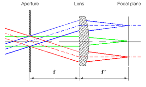
Figure 1: Imaging of bundles of elementary parallel rays to form a directions image in the back focal plane of a positive thin lens. This transformation can easily be deduced from two simples rules for the thin positive lens:
- the rays through the center of the lens remain unchanged,
- the rays through the front focal point are transformed into parallel rays.
The object of measurement is usually located in the front focal plane of the lens. In order to select a specific area of interest on the object (i.e., definition of a measuring spot, or field of measurement) an aperture can be placed on top of the object. In this configuration only rays from the measuring spot (aperture) hit the lens.
The image of the aperture is projected to infinity while the image of the directional distribution of the light passing through the aperture (i. e. directions image) is generated in the back focal plane of the lens. When it is not considered appropriate to place an aperture into the front focal plane of the lens, i.e., on the object, the selection of the measuring spot (field of measurement) can also be achieved by using a second lens. An image of the object (located in the front focal plane of the first lens) is generated in the back focal plane of the second lens. The magnification, M, of this imaging is given by the ratio of the focal lengths of the lenses L1 and L2, M = f2 / f1.
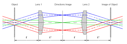
Figure 2: Formation of an image of the object (aperture) by addition of a second lens. The field of measurement is determined by the aperture located in the image of the object. A third lens transforms the rays passing through the aperture (located in the plane of the image of the object) into a second directions image which may be analyzed by an image sensor (e.g., electronic camera).
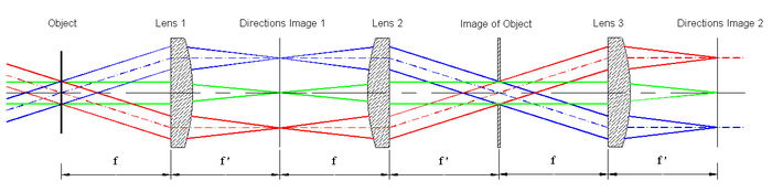
Figure 3: Schematic raytracing of a complete conoscope: formation of the directions image and imaging of the object. The functional sequence is as follows:
- the first lens forms the directions image (transformation of directions into locations),
- the second lens together with the first projects an image of the object,
- the aperture allows selection of the area of interest (measuring spot) on the object,
- the third lens together with the second images the directions image on a 2-dimensional optical sensor (e.g., electronic camera).
This simple arrangement is the basis for all conoscopic devices (conoscopes). It is not straight forward however to design and manufacture lens systems that combine the following features:
- maximum angle of light incidence as high as possible (e.g., 80°),
- diameter of measuring spot up to several millimeters,
- achromatic performance for all angles of inclination,
- minimum effect of polarization of incident light.
Design and manufacturing of this type of complex lens system requires assistance by numerical modelling and a sophisticated manufacturing process.
Modern advanced conoscopic devices are used for rapid measurement and evaluation of the electro-optical properties of LCD-screens (e.g., variation of luminance, contrast and chromaticity with viewing direction).
References
- ^ Ch. Maugin: "Sur les cristaux liquides de Lehmann", Bull. Soc. Min. 34(1911), pp. 71
Literature
- Pochi Yeh, Claire Gu: "Optics of Liquid Crystal Displays", John Wiley & Sons 1999, 4.5. Conoscopy, pp. 139
- Hartshorne & Stuart: "Crystals and the Polarizing Microscope", Arnold, London, 1970, 8: The Microscopic Examination of Crystals, (ii) Conoscopic Observations (in convergent light)
- C. Burri: "Das Polarisationsmikroskop", Verlag Birkhäuser, Basel 1950
External links
Categories:


Wikimedia Foundation. 2010.