- Chuck (engineering)
-
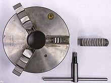 Self-centering three-jaw chuck and key with one jaw removed and inverted showing the teeth that engage in the scroll plate. The scroll plate is rotated within the chuck body by the key, the scroll engages the teeth on the underside of the jaws which moves the three jaws in unison, to tighten or release the workpiece.
A chuck is a specialized type of clamp used to hold an object,[1] usually an object with radial symmetry, especially a cylindrical object. It is most commonly used to hold a rotating tool (such as the drill bit in a power tool) or a rotating workpiece (such as the bar or blank in the headstock spindle of a lathe). Some chucks can also hold irregularly shaped objects (ones that lack radial symmetry). In some applications, the tool or workpiece being held by the chuck remains stationary while another tool or workpiece rotates (for example, a drill bit in the tailstock spindle of a lathe, or a round workpiece being milled by a milling cutter).
Many chucks have jaws, which are dogs that are arranged in a radially symmetrical pattern (like the points of a star) to hold the tool or workpiece. Often the jaws will be tightened or loosened with the help of a chuck key, which is a wrench-like tool made for the purpose. Many jawed chucks, however, are of the keyless variety, and their tightening and loosening is by hand force alone. Keyless designs offer the convenience of quicker and easier chucking and unchucking at the expense of higher gripping force to hold the tool or workpiece. Collet chucks, rather than having jaws, have collets, which are flexible collars or sleeves that fit closely around the tool or workpiece and grip it when squeezed.
A few chuck designs are more complex yet, and they involve specially shaped jaws, higher numbers of jaws, quick-release mechanisms, or other special features.
Some chucks, such as magnetic chucks and vacuum chucks, are of a different sort from the radially symmetrical mechanical clamps mentioned above. Instead, they may be surfaces (typically flat) against which workpieces or tools are firmly held by magnetic or vacuum force.
To chuck a tool or workpiece is to hold it with a chuck, in which case it has been chucked. Machining work whose workholding involves a chuck is often called chucking work. Automatic lathes that specialize in chucking work are often called chuckers.
Contents
Types
Jawed chucks
Self-centering
A self-centering chuck, also known as a scroll chuck,[2] uses dogs (usually called jaws), interconnected via a scroll gear (scroll plate), to hold onto a tool or workpiece. Because they most often have three jaws, the term three-jaw chuck without other qualification is understood by machinists to mean a self-centering three-jaw chuck. The term universal chuck also refers to this type. These chucks are best suited to grip circular or hexagonal cross-sections when very fast, reasonably accurate (±0.005 in TIR) centering is desired.
Sometimes this type of chuck has four or six jaws instead of three. More jaws confer more secure grip (if the work is truly cylindrical) and thin-walled work will deform less. Four jaws are also useful for square bar work.
Independent-jaw (non-self-centering) chucks with three jaws also can be obtained.
There are hybrid self-centering chucks that have adjustment screws that can be used to further improve the concentricity after the workpiece has been gripped by the scroll jaws. This feature is meant to combine the speed and ease of the scroll plate's self-centering with the runout-eliminating controllability of an independent-jaw chuck. The most commonly used name for this type is a brand name, Set-Tru. To avoid undue genericization of that brand name, suggestions for a generic name have included "exact-adjust".[3]
Three-jaw chucks can often be found on lathes and indexing heads.
Drill chuck
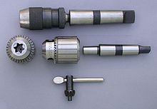 Top: an assembled keyless chuck. The tightening action of this chuck style is performed by twisting the body using firm hand pressure only. While convenient, this feature can cause the chuck to loosen if too much torque is applied. Bottom: the traditional keyed style of drill chuck with its key. The arbor is shown separately to the right. These chucks require a key to provide the necessary torque to tighten and loosen the jaws. The rotary action of the key turns the outer body which acts on an internal screw; this in turn moves the threaded jaws in or out along a tapered surface. The taper allows the jaws to encompass various sizes of drill shanks. The end view shows the three small jaws that slide within the body.
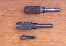 Two pin chucks. The top one is assembled, the lower one shows the body and nose cap assembled with the collet piece below it.
A drill chuck is a specialised self-centering, three-jaw chuck, usually with capacity of less than 0.5 in (13 mm) and rarely greater than 1 in (25 mm), used to hold drill bits or other rotary tools. This is the type of chuck that a machining layperson is most likely to be familiar with.
Some high precision chucks use ball thrust bearings to reduce friction in the closing mechanism and maximizing drilling torque. One brand name for this type of chuck, which is often genericized in colloquial use although not in catalogs, is Super Chuck.
A pin chuck is a specialized chuck designed to hold small drills (less than 1 mm (0.039 in) in diameter) that could not be held securely in a normal drill chuck. The drill is inserted into the pin chuck and tightened, the pin chuck is then inserted into the larger drill chuck so that the operation can continue. Pin chucks are also found on high speed rotary tools, such as die grinders and jig grinders.
Independent-jaw
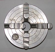 Independent four-jaw chuck, also known as a universal chuck, with the jaws independently set. The key is used to adjust each jaw separately.
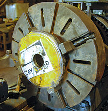 An older and larger 4 jaw chuck. Note how it is able to grip an irregularly cut piece of used metal. Though not found on small chucks it is common for larger chucks (the one in the second photo was made around 1900 and is 24" in diameter) to have many of the features of a faceplate. The jaws are stepped on one side and full height for gripping on the other and are reversible. Generally the jaws are usable for holding either outside as shown here, or inside as in gripping the inside of a pipe.
On an independent-jaw chuck, each jaw can be moved independently. Because they most often have four jaws, the term four-jaw chuck without other qualification is understood by machinists to mean a chuck with four independent jaws. The independence of the jaws makes these chucks ideal for (a) gripping non-circular cross sections and (b) gripping circular cross sections with extreme precision (when the last few hundredths of a millimeter [or thousandths of an inch] of runout must be manually eliminated). The non-self-centering action of the independent jaws makes centering highly controllable (for an experienced user), but at the expense of speed and ease. Four-jaw chucks are almost never used for tool holding. Four-jaw chucks can be found on lathes and indexing heads.
Self-centering chucks with four jaws also can be obtained. Although these are often said to suffer from two disadvantages: inability to hold hex stock, and poor gripping on stock which is oval, only the latter is true. Even with three jaw self centering chucks, work which is not of uniform section along the work (and which is not free of spiral or 'wind')should not be gripped, as the jaws can be strained and the accuracy permanently impaired.
Four-jaw chucks can easily hold a workpiece eccentrically if eccentric features need to be machined.
Specialty jawed types (two-, six-, eight-jaw; other)
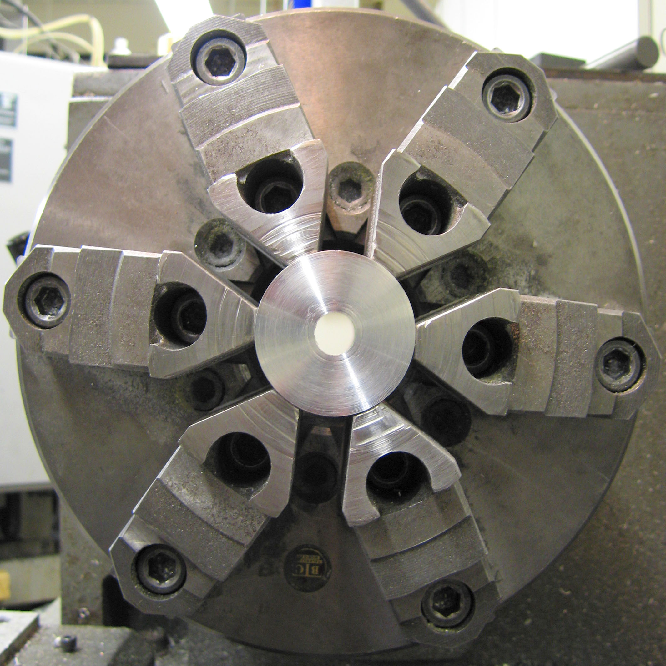
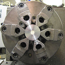 Chuck with six jaws
For special purposes, and also the holding of fragile materials, chucks are available with six or eight jaws. These are usually of the self-centering design, and may be built to very high standards of accuracy.
Two-jaw chucks are available and can be used with soft jaws (typically an aluminium alloy) that can be machined to conform to a particular workpiece. It is a short conceptual leap from these to faceplates holding custom fixtures, wherein the part is located against fixed stops and held there with toggle clamps or toe clamps.
Jaw construction
Many chucks have removable jaws (often the top part is removable leaving the base or 'master jaw' assembled with the scroll), which allows the user to replace them with new jaws, specialized jaws, or soft jaws. Soft jaws are made of soft materials such as soft (unhardened) metal, plastic, or wood. They can be machined as needed for particular setups. The typical interface between the master jaw and the removable jaw is a matching pair of serrated surfaces, which, once clamped by the mounting screws, cannot allow relative slipping between the two parts.
Collet
Main article: ColletA collet, one type of chuck, is a sleeve with a (normally) cylindrical inner surface and a conical outer surface. The collet can be squeezed against a matching taper such that its inner surface contracts to a slightly smaller diameter, squeezing the tool or workpiece whose secure holding is desired. Most often this is achieved with a spring collet, made of spring steel, with one or more kerf cuts along its length to allow it to expand and contract. An alternative collet design is one that has several tapered steel blocks (essentially tapered gauge blocks) held in circular position (like the points of a star, or indeed the jaws of a jawed chuck) by a flexible binding medium (typically synthetic or natural rubber). The Jacobs Rubber-Flex brand is a name that most machinists would recognize for this type of collet chuck system.
Regardless of the collet design, the operating principle is the same: squeeze the collet radially against the tool or workpiece to be held, resulting in high static friction. Under correct conditions, it holds quite securely. Almost all collet chucks achieve the radial squeezing motion via moving one or more male-female pairs of tapered (conical) surfaces axially, which produces the radial squeezing in a highly concentric manner. Depending on the collet design, it can be either pulled (via a threaded section at the rear of the collet) or pushed (via a threaded cap with a second taper) into a matching conical socket to achieve the clamping action. As the collet is forced into the tapered socket, the collet will contract, gripping the contents of the inner cylinder. (The axial movement of cones is not mandatory, however; a split bushing squeezed radially with a linear force—e.g., set screw, solenoid, spring clamp, pneumatic or hydraulic cylinder—achieves the same principle without the cones; but concentricity can only be had to the extent that the bushing's diameters are perfect for the particular object being held. Thus only in toolroom contexts, such as machine tool tooling creation and setup, is this common.)
One of the corollaries of the conical action is that collets may draw the work axially a slight amount as they close. Collet chuck systems that make no provision to prevent this draw-in are often called draw-in collet chucks, in contrast to systems which circumvent this movement, usually by pushing the tapered closing ring toward the collet rather than pulling the collet into the ring. Such non-draw-in types are often called "dead-length" or "non-draw-in" collet chucks. Draw-in is not always a problem, but avoiding it can be helpful on some work where failing to account for it might result in inaccuracy on part overall length, shoulder lengths, etc.
Collets are most commonly found on milling machines, lathes, wood routers, precision grinders, and certain handheld power tools such as die grinders and rotary tools. There are many different systems, common examples being the ER, 5C, and R8 systems. Collets can also be obtained to fit Morse or Brown and Sharpe taper sockets.
Typically collets offer higher levels of precision and accuracy than self-centering chucks, and have a shorter setting up time than independent-jaw chucks. The penalty is that most collets can only accommodate a single size of workpiece. An exception is the ER collet which typically has a working range of 1 mm (about 0.04 in).
Collets usually are made to hold cylindrical work, but are available to hold square, hexagonal or octagonal workpieces. While most collets are hardened, "emergency" collets are available that can be machined to special sizes or shapes by the user. These collets can be obtained in steel, brass, or nylon. Step collets are available that are machinable to allow holding of short workpieces that are larger than the capacity of normal collets.
Special Direct System (SDS)
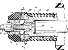 Diagram of an SDS chuck
Developed by Bosch in 1975 for hammer drills, the SDS uses a cylindrical shank on the tool, with indentations to be held by the chuck.[4] A tool is inserted into the chuck by pressing in, and is locked in place until a separate lock release is used. The rotary force is supplied through wedges that fit into two or three open grooves. The hammer action actually moves the bit up and down within the chuck since the bit is free to move a short distance. Two sprung balls fit into closed grooves, allowing movement whilst retaining the bit. SDS relies on a tool having the same shank diameter as the chuck; there are three standard sizes:
- SDS-Plus: a 10 mm shank with two open grooves held by the driving wedges and two closed grooves held by locking balls. This is the most common size and takes a hammer up to 4 kg. The wedges grip an area of 75 mm² (0.116 sq in) and the shank is inserted 40 mm into the chuck.[5]
- SDS-top: a 14 mm shank similar to SDS-plus, designed for hammers from 2 to 5 kg. The grip area is increased to 212 mm² (0.329 sq in) and the shank is inserted 70 mm. This size is uncommon.[6]
- SDS-max: an 18 mm shank with three open grooves and locking segments rather than balls. It is designed for hammers over 5 kg. The wedges grip an area of 389 mm² (0.603 sq in) and the shank is inserted 90 mm.[7]
Many SDS drills have a "rotation off" setting, which allows the drill to be used for chiselling. The name SDS comes from the German steck, dreh, sitzt (insert, twist, fits). German-speaking countries may use Spannen durch System (Clamping System), though Bosch uses Special Direct System for international purposes.[8]
Chucks with both indexable positioning and indexable clamping
Commercial production machining now makes use of increasingly advanced chucks which have not only indexable positioning but also indexable clamping.[9] Both functions are typically hydraulically controlled. The clamping is often done with each pair of jaws consisting of one fixed jaw and one movable jaw (hydraulically actuated), thematically similar to advanced milling vises. This method of clamping brings the high precision and repeatability of such vises to a chucking application. Such chucks offer the centering precision of traditional independent-jaw chucks with the chucking speed and ease of traditional three-jaw self-centering scroll chucks. They have expensive initial cost (compared with traditional chucks), but such initial cost pays for itself and then lowers ongoing marginal costs in commercial production-run environments.
It is also possible nowadays to build CNC chucks in which the position and clamping pressure of each jaw can be precisely controlled with CNC, via closed-loop positioning and load monitoring. In essence, each jaw is one independent CNC axis, a machine slide with a leadscrew, and all four or six of them can act in concert with each other. Although this idea is conceptually interesting, the simpler chucking systems mentioned in the previous paragraph are probably a marketplace winner over this alternative for most applications, because they supply the same capabilities via a simpler, less expensive solution.
Magnetic
Used for holding ferromagnetic workpieces, a magnetic chuck consists of an accurately centered permanent magnet face. Electromagnets or permanent magnets are brought into contact with fixed ferrous plates, or pole pieces, contained within a housing. These pole pieces are usually flush with the housing surface. The part (workpiece) to be held forms the closing of the magnetic loop or path, onto those fixed plates, providing a secure anchor for the workpiece.
Electrostatic
Commonly used for holding silicon wafers during lithography processes, an electrostatic chuck comprises a metal base-plate and a thin dielectric layer; the metal base-plate is maintained at a high-voltage relative to the wafer, and so an electrostatic force clamps the wafer to it. Electrostatic chucks may have pins, or mesas, the height of which is included in the reported dielectric thickness; a design by Sandia National Laboratory uses a patterned silicon-dioxide dielectric to form the pins.[10]
Vacuum
A vacuum chuck is primarily used on non-ferrous materials, such as copper, bronze, aluminum, titanium, plastics, and stone. In a vacuum chuck, air is pumped from a cavity behind the workpiece, and atmospheric pressure provides the holding force. Vacuum produces a hold down pressure of 14.7 psi (101 kPa) at sea level, decreasing at higher elevations where the atmospheric pressure is lower. The decrease in holding pressure is roughly 0.5 psi per 1000' above sea level.[11]
Mounting methods
Connecting chucks to the spindles or tables of machine tools or power tools has been accomplished in many ways over the years.
Mounting of drill chucks
- A threaded arbor may screw into the chuck body.
- A tapered arbor (with a self-holding taper) may be pressed into the chuck body.
- Removal and insertion may involve various tools or methods:
- Tools: vise (especially with a wooden jig or soft jaw made for this purpose); hammer (especially nonmarring hammer or rubber mallet); arbor press or shop press (the latter two require skill to avoid damaging the chuck).
- Methods: heating (via heat guns, blow torches, or ovens) and cooling (via kitchen freezers, winter weather, or decompression of compressed air or nitrogen).
- Removal and insertion may involve various tools or methods:
- A drill chuck may have a hollow body that threads directly onto a lathe's threaded spindle nose. (These are fairly rare, especially nowadays.)
Mounting of large jawed chucks
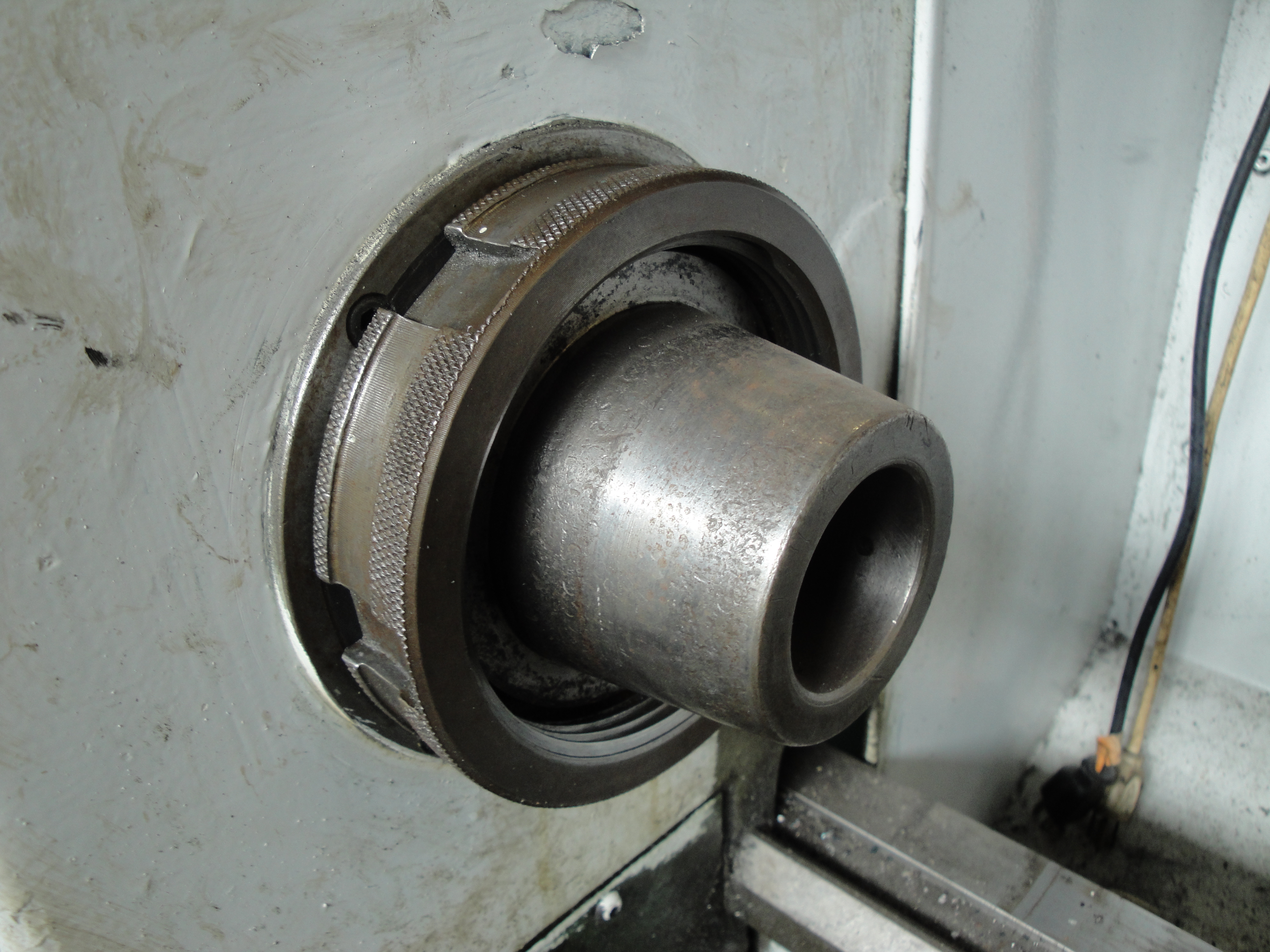
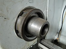 Taper spindle nose with threaded retention. The retainer ring is wrenched with a spanner wrench.
- A backplate with threads may screw onto a threaded spindle nose (for lathe work) or onto an adapter plate with the same nose, to be mounted on the table of milling machines or surface grinding machines. This "threaded spindle nose" type of mounting was the typical method in the 19th century through 1930s. It is simple and useful, but the degree of control of concentricity is not quite good enough to be foolproof for high-speed, high-precision work (high precision can be achieved, but the time and skill involved in the setups makes it a poor choice now that better options exist, such as the cam-lock spindle noses described below). Threaded spindle noses are still built on new machine tools, but only of the low-end variety (hobbyist, least-expense MRO, etc). High-capital manufacturing (where high upfront expense yields lowest possible unit expense for mid- to high-volume part counts of high-precision parts) has moved away from this type of mounting. The exact-adjust (Set-Tru) concept is one way to chase high concentricity on threaded spindle noses with some relative degree of ease.
- A backplate with a female (self-releasing) taper may seat on the matching male taper of the taper(ed) spindle nose (for lathe work) or of an adapter plate with the same nose, to be mounted on a table. This system improves the repeatability of the mounting concentricity down to a very small total indicated runout (TIR) value. Subtypes:
- The chuck may be held against the taper with a threaded retainer ring (large thin nut), typically wrenched with a spanner wrench of the pin or hook variety. The peak of popularity for building this type of spindle nose was probably the 1940s and 1950s.
- The chuck may be held against the taper with cam-lock posts that wedge into a stuck-fast position. Industry-standard spindle nose designs allow wide interchangeability. This cam lock spindle nose system replaced the earlier systems on most machine tools in the 1960s.
Mounting of collet chucks
- For collect chucks mounted on backplates, all of the same methods above are applicable.
- Many lathes that run collet chucks have dedicated collet-closer setups whereby there is no backplate, and the spindle nose contains the female taper for either the collet's male outer taper, or a sleeve that will hold it. A hollow drawbar passes back through the headstock to its back side, where a closer mechanism is mounted. The latter allows easy, rapid opening and closing of the collet. The drawbar's inner diameter determines the through-the-spindle bar diameter capacity of the lathe. Some collet-closer systems even allow opening and closing without stopping the spindle rotation. The closer on a manual lathe is either lever-style or handwheel-style. The closer on a CNC lathe is powered (electric, hydraulic, or pneumatic), and it may be controlled by various means: a foot pedal that the operator steps on when desired; a line in the program (for opening and closing under program control); or a button on the control panel.
History
The original forms of workholding on lathes were between-centers holding and ad-hoc fastenings to the headstock spindle. The spike-style centers used on wood lathes even today are an ancient method. Ad-hoc fastening methods in centuries past included anything from pinning with clenching or wedging; nailing; lashing with cords of leather or fiber; dogging down (again involving pinning/wedging/clenching); or other types. Faceplates have probably been around at least since the era of medieval clock makers.
Tooling that we today would call chucks seems likely to have evolved from faceplate work, as workers who were using faceplates for repetitive work began to envision types of clamps or dogs for the faceplate that could be opened and closed in more convenient ways than repeated total disassembly and reassembly.
Some names that are known to figure in the history of chuck development include Simon Fairman and Austin F. Cushman (who may have been uncle/nephew or father-in-law/son-in-law) and Arthur Irving Jacobs. Apparently, Fairman invented the first piece of tooling that we today would call a lathe chuck, and Cushman invented the first self-centering lathe chuck. Cushman's name lived on via an eponymous company. Judging from a historical sketch given by the Jacobs Chuck Manufacturing Company[12] (a well-known brand in the drill chuck field), Arthur I. (A.I.) Jacobs was apparently the person who further developed Cushman's self-centering scroll-gear idea into the type of drill chuck that we know today (for which his company would later be famous). A.I. Jacobs's patent of 1902 (U.S. Patent 709,014) appears to be the principal patent. The term "drill chuck" clearly did not originate with him, but it seems that his new type of drill chuck long ago displaced all earlier types, which apparently lacked the angled jaw movement and outer sleeve that we now consider the norm.
See also
References
- ^ http://wdturner.com/ChuckCollet.pdf
- ^ Cubberly, W. (1989). Tool and Manufacturing Engineers Handbook. Society of Manufacturing Engineers. p. 23‐16. ISBN 9780872633513. http://books.google.com/books?id=NRXnXmFRjWYC&&pg=SA23-PA16.
- ^ Whitney, Gregory (Feb-Mar 2011), "How to make an inexpensive "exact adjust" 5C collet chuck", Machinist's Workshop (Traverse City, MI, USA: Village Press Inc) 24 (1): 11–15, http://www.homeshopmachinist.net/.
- ^ US 4123074
- ^ "SDS-plus tool insertion system". Encyclopedia of technical terms (A-Z). Archived from the original on 2006-06-26. http://web.archive.org/web/20060626233129/http://www.ewbc.de/onlinelearning/eopt/data/nid18185_10668/18185.html. Retrieved 2006-04-12.
- ^ "SDS-top". Encyclopedia of technical terms (A-Z). Archived from the original on 2006-06-26. http://web.archive.org/web/20060626233143/http://www.ewbc.de/onlinelearning/eopt/data/nid18185_10669/18185.html. Retrieved 2006-04-12.
- ^ "SDS-max". Encyclopedia of technical terms (A-Z). Archived from the original on 2006-06-26. http://web.archive.org/web/20060626233005/http://www.ewbc.de/onlinelearning/eopt/data/nid18185_10667/18185.html. Retrieved 2006-04-12.
- ^ "SDS". Lexikon der Elektrowerkzeuge. Archived from the original on 2006-06-26. http://web.archive.org/web/20060626233117/http://www.ewbc.de/onlinelearning/eopt/data/nid0_12112/18183.html. Retrieved 2006-04-12. (German language)
- ^ Brown 2011.
- ^ Lab News. "Electrostatic chuck". Sandia.gov. http://www.sandia.gov/LabNews/LN03-27-98/chuck_story.html. Retrieved 2010-01-13.
- ^ http://www.vacuumchuck.com/tutorials/
- ^ Jacobs Chuck Manufacturing Company, About Jacobs, http://www.jacobschuck.com/aboutus.asp, retrieved 2011-01-14
Bibliography
- Brown, Chris (2011-04-25), "A close look at indexable chucks", Production Machining, http://www.productionmachining.com/articles/a-close-look-at-indexable-chucks.
Metalworking Machining and computing Computer-aided engineering Drilling and threading Grinding and lapping Abrasive · Angle grinder · Bench grinder · Coated abrasives · Cylindrical grinder · Diamond plate · Flick grinder · Dresser · Grinding · Grinding machine · Grinding wheel · Jig grinder · Lapping · Sanding · Sharpening stone · Spark testing · Surface grinder · Tool and cutter grinderMachining and milling Electrical discharge machining · Electrochemical machining · Endmill · Engraving · Hobbing · Lathe · Machine tool · Machining · Milling cutter · Milling machine · Planer · Pantograph · ShaperMachine tooling Angle plate · Chuck · Collet · Jig · Fixture · Indexing head · Lathe center · Machine taper · Magnetic base · Mandrel · Rotary table · WigglerTerminology Casting · Fabrication · Forming · Jewellery · Machining · Metallurgy · Smithing · Tools and terminology · WeldingCategories:- Clamps
- Lathes
- Machine tools
- Woodworking clamps


Wikimedia Foundation. 2010.