Open circuit test

Open circuit test

The Open circuit test, or "no-load test", is one of the methods used in electrical engineering to determine the no load impedance in the excitation branch of a real transformer.

Circuit diagram for Open Circuit test

Contents

Method

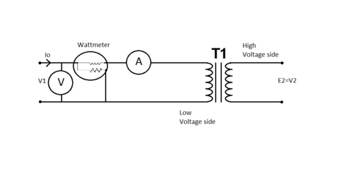
The secondary of the transformer is left open-circuited. A wattmeter is connected to the primary. An ammeter is connected in series with the primary winding. A voltmeter is optional since the applied voltage is same as the voltmeter reading. Rated voltage is applied at primary.

If the applied voltage is normal voltage then normal flux will be set up. As the Iron loss is a function of applied voltage, normal iron loss will occur. Hence the iron loss is maximum at rated voltage. This maximum iron loss is measured using the wattmeter. Since the impedance of the series winding of the transformer is very small compared to that of the excitation branch, all of the input voltage is dropped across the excitation branch. Thus the wattmeter measures only the iron loss.

Since the secondary of the transformer is open, the primary draws only no load current. This no load current is negligible. As the copper losses depend on current they can be neglected.

Current, voltage and power are measured at the primary winding to ascertain the admittance and power factor angle.

Another method of determining the series impedance of a real transformer is the short circuit test.

Calculations

The current \mathbf{I_0} is very small.

If \mathbf{W} is the wattmeter reading then,


\mathbf{W} = \mathbf{V_1} \mathbf{I_0} \cos \phi_0

The above equation can be rewritten as,

\cos \phi_0 = \frac {\mathbf{W}} {\mathbf{V_1} \mathbf{I_0}}

Thus,

\mathbf{I_m} = \mathbf{I_0} \sin \phi_0
\mathbf{I_w} = \mathbf{I_0} \cos \phi_0

Impedance

By using the above equations, \mathbf{X_0} and \mathbf{R_0} can be calculated as,

\mathbf{X_0} = \frac {\mathbf{V_1}} {\mathbf{I_m}}


\mathbf{R_0} = \frac {\mathbf{V_1}} {\mathbf{I_w}}

Thus,

\mathbf{Z_0} = \sqrt {\mathbf{R_0}^2 +\mathbf{X_0}^2}

or

\mathbf{Z_0} = \mathbf{R_0} + \mathbf{j} \mathbf{X_0}

Admittance

The admittance is the inverse of impedance. Therefore,

\mathbf{Y_0} = \frac {1} {\mathbf{Z_0}}

The conductance \mathbf{G_0} can be calculated as,

\mathbf{G_0} = \frac {\mathbf{W}} {\mathbf{V_1}^2}

Hence the susceptance,

\mathbf{B_0} = \sqrt {\mathbf{Y_0}^2 -\mathbf{G_0}^2}

or

\mathbf{Y_0} = \mathbf{G_0} + \mathbf{j} \mathbf{B_0}


Here,

\mathbf{W} is the wattmeter reading

\mathbf{V_1} is the applied rated voltage

\mathbf{I_0} is the no load current

\mathbf{I_m} is the magnetizing component of no load current

\mathbf{I_w} is the core loss component of no load current

\mathbf{Z_0} is the exciting impedance

\mathbf{Y_0} is the exciting admittance

References

  • Kosow (2007). Electric Machinery and Transformers. Pearson Education India. 
  • Smarajit Ghosh (2004). Fundamentals of Electrical and Electronics Engineering. PHI Learning Pvt. Ltd.. 
  • Wildi, Wildi Theodore (2007). Electrical Machines , Drives And Power Systems, 6th edtn.. Pearson. 

See also


Wikimedia Foundation. 2010.

Игры ⚽ Поможем решить контрольную работу

Look at other dictionaries:

  • open-circuit test — tuščiosios veikos bandymas statusas T sritis radioelektronika atitikmenys: angl. no load test; open circuit test vok. Leerlaufversuch, m rus. испытание на холостом ходу, n; опыт холостого хода, m pranc. essai à circuit ouvert, m; essai à vide, m …   Radioelektronikos terminų žodynas

  • Open circuit — The term Open circuit may refer to: Open circuit scuba, a type of SCUBA diving equipment where the user breathes from the set and then exhales to the surroundings without recycling the exhaled air Open circuit test, a method used in electrical… …   Wikipedia

  • Open-circuit time constant method — The open circuit time constant method is an approximate analysis technique used in electronic circuit design to determine the corner frequency of complex circuits. It also is known as the zero value time constant technique. The method provides a… …   Wikipedia

  • Fixtureless in-circuit test — (FICT) is a cost effective alternative to a bed of nails tester for in circuit testing of low to medium volumes of printed circuit board assemblies. It relies on a computerized optical inspection of the circuit assembly and positionable test… …   Wikipedia

  • Test probe — Typical passive oscilloscope probe being used for testing an integrated circuit. A test probe (test lead, test prod, or scope probe) is a physical device used to connect electronic test equipment to the device under test (DUT). They range from… …   Wikipedia

  • Circuit Showdown — Category Auto Racing Series Country or region Philippines Inaugural season 2010 Official website …   Wikipedia

  • Circuit de Nevers Magny-Cours — bis 1987 Circuit Jean Behra Adresse: Circuit de Nevers Magny Cours Technopôle 58 470 Magny Cours …   Deutsch Wikipedia

  • Open Graphics Project — Website http://wiki.opengraphics.org/tiki index.php Commercial? Yes Type of project Open hardware …   Wikipedia

  • Test Drive Unlimited 2 — Éditeur Atari Développeur Eden Games Date de sortie …   Wikipédia en Français

  • essai à circuit ouvert — tuščiosios veikos bandymas statusas T sritis radioelektronika atitikmenys: angl. no load test; open circuit test vok. Leerlaufversuch, m rus. испытание на холостом ходу, n; опыт холостого хода, m pranc. essai à circuit ouvert, m; essai à vide, m …   Radioelektronikos terminų žodynas

Share the article and excerpts

Direct link
Do a right-click on the link above
and select “Copy Link”