- Coupling (railway)
-
 Knuckle (AAR Type "E") couplers in use
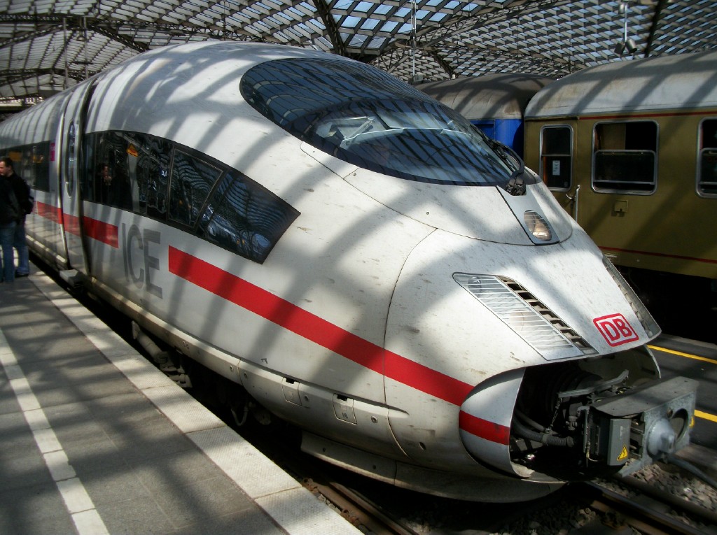
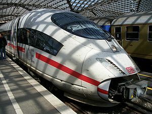 ICE coupler
A coupling (or a coupler) is a mechanism for connecting rolling stock in a train. The design of the coupler is standard, and is almost as important as the railway gauge, since flexibility and convenience are maximised if all rolling stock can be coupled together.
The equipment that connects the couplings to the rolling stock is known as the draft gear.
Contents
Nomenclature
The different types of coupling do not always have formal or official names, which makes descriptions of the couplings in use on any railway system problematic.
Buffers and chain
 Traditional buffer-and-chain coupler
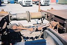 Two cars coupled
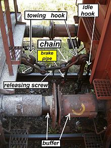 Chain coupler detail (train in shunting mode)
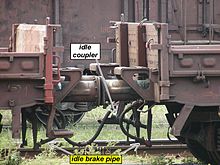 Cars coupled in ride mode
The standard type of coupling on railways following the British tradition is the buffer and chain coupling used on the pioneering Planet class locomotive of the Liverpool and Manchester Railway of 1830. These couplings followed earlier tramway practice but were made more regular. The vehicles are coupled by hand using a hook and links with a turnbuckle-like device that draws the vehicles together. In Britain, this is called a screw coupling. Vehicles have buffers, one at each corner on the ends, which are pulled together and compressed by the coupling device. This arrangement limits the slack in trains and lessens shocks. In contrast, Janney couplers encourage comparatively violent encounters in order to engage the coupling fully. The earliest buffers were fixed extensions of the wagon frames, but later spring buffers were introduced.
Inefficient and slow, the European system is relatively unsafe because it requires manual coupling between vehicles, exposing workers to the risk of being crushed. However, there is no need for the worker to go between vehicles while they are moving, which is an improvement over the link-and-pin types.
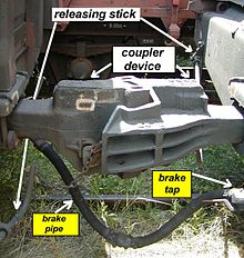
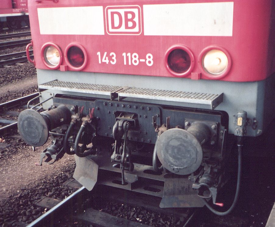
This coupling type is the standard in European countries (except the former Soviet Union, where the SA-3 automatic coupler is used). Coupling is done by a worker, who must climb between the cars. First he turns a releasing screw (an aid with two opposite windings, and it does not uncouple the train itself) to the loose position, and then he can hang the chain on the hook. After hanging the chain on the towing hook the releasing screw must be turned to the tight position. When the coupler is uncoupled, it must be hung on the idle hook to prevent damage to itself or the brake pipes. Only shunting is permitted with a dangling chain. Disconnected brake pipes must be hung on hooks. (The picture shows two coupled cars, with a single brake pipe.)
The hooks and chain hold the carriages together, while the buffers keep the carriages from banging into each other so that no damage is caused. The buffers can be "dumb" or spring-loaded. That means there are no run-in forces on the coupler. The other benefit compared with automatic couplers is that its lesser slack causes smaller forces on curves; there is a lower probability of a broken coupler in a curve than with automatic couplers. The disadvantage is the smaller mass of the freight that can be hauled by that coupler (maximum 3,000 t/2,953 long tons; 3,307 short tons).
Early rolling stock was often fitted with a pair of auxiliary chains as a backup if the main coupling failed. This made sense before the fitting of continuous fail-safe braking systems.
On railways where rolling stock always pointed the same way, the chain might be mounted at one end only, as a small cost- and weight-saving method.
On German and Scandinavian railways, the left buffer is flatter than the right one, which is slightly more rounded. This provides better contact between the buffers than would be the case if both buffers were slightly rounded.
Three-link couplings
A peculiarly British institution was the "loose-coupled" freight train. This used three-link chain couplings with no means of drawing the wagons together: since such trains were not fitted with an automatic through-train braking system there were no pipes to connect between the vehicles. The couplings in the train were kept taut by the last vehicle of the train being a heavily ballasted guard's van with its brakes set slightly on. This helped prevent snapped couplings. Such trains travelled at low speeds and were phased out in the 1970s.[citation needed]
An improvement on this is the "Instanter" coupling, in which the middle link of a three link chain is specially shaped so that when lying "prone" it provides enough slack to make coupling possible, but when this middle link is rotated 90 degrees the length of the chain is effectively shortened, reducing the amount of slack without the need to wind a screw. The closeness of the coupling allows the use of inter-vehicle pipes for train brakes. It also has the advantage that it can be operated entirely from the side of the wagons using a shunter's pole and is therefore safer when shunting work is under way. These couplings are still prevalent in UK freight trains today.[citation needed]
Center-buffer-and-chain(s)
 Coupling of Benin 1,000 mm (3 ft 3 3⁄8 in) gauge - Centre buffer and twin chains
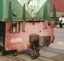 Centre buffer and screw chain below; Cambodia 1,000 mm (3 ft 3 3⁄8 in) gauge
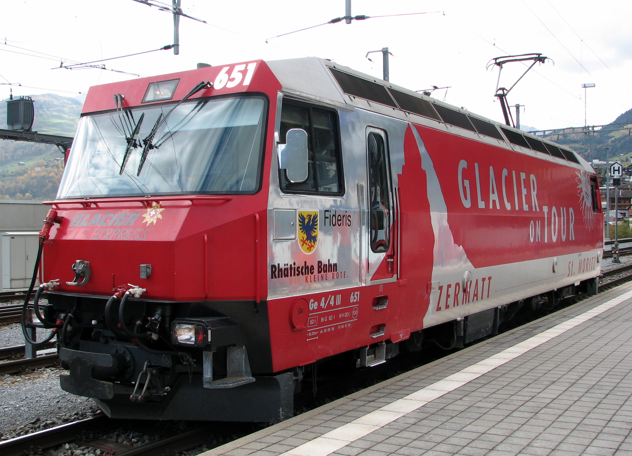
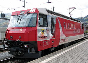 The narrow gauge "Centre-buffer-&-chains" coupler of the Rhätische Bahn, called Balancierhebelkupplung
On some narrow-gauge lines in Europe a simplified version is used, consisting of a single central buffer with a chain underneath. Sometimes there are two chains, one on each side of the coupler. The chain usually contains a screw-adjustable link to allow close coupling. These variants are also used elsewhere. On sharp curves, a single centre buffer is less likely to be subject to buffer-locking.
Buffers-and-chain on the narrow gauge
Perhaps because of the buffer-locking problem occasioned by sharp curves – and Carl Pihl's successful promotion of the single-buffer Norwegian coupler that he designed to overcome this – conventional buffers-and-chain coupling is rarely employed on narrow-gauge systems: notable exceptions being the railway networks of Senegal/Mali and Côte d'Ivoire/Burkina Faso in Africa, and Queensland and Tasmania in Australia.
Problems with buffers and chain
Buffer-locking
The buffers and chain coupling system has a maximum load much less than that of the Janney coupling. Also, on sharp reverse curves, the buffers can get buffer-locked by slipping over – and onto the back of – an adjacent buffer. Although careful track design makes this occurrence rare, an accident at a Swiss station in the 1980s was caused by buffer-locked wagons.[citation needed] Buffer-lock could be caused on the very sharp turnouts by the older, rounded buffers. The newer buffers are rectangular and they are wider than they are tall. They are not so flat, so they rarely cause buffer-locking.[citation needed]
Variation with gauge
The width between the buffers tends to increase as the gauge increases or decrease as the gauge decreases, so that if wagons are changed from one gauge to another, the buffers will no longer match. This occurs because the buffers are originally extensions of the frames, which are spaced according to the gauge. Conversely, as gauge reduces, the distance between the buffers reduces also. The height of the buffers is usually lower on narrow gauge railways, corresponding to the generally lower height of the rolling stock.
Dimensions
Dimensions showing variation by gauge.
- Standard gauge - England
- Height: 3 ft 5 1⁄2 in (1,054 mm)
- Separation: 6 ft (1,829 mm) [1]
- Metre gauge - Senegal/Mali Jane's World Railways 1969 - 1970 edition
- Height: 293⁄4 in (756 mm)
- Separation: 491⁄8 in (1,250 mm)
Link and pin
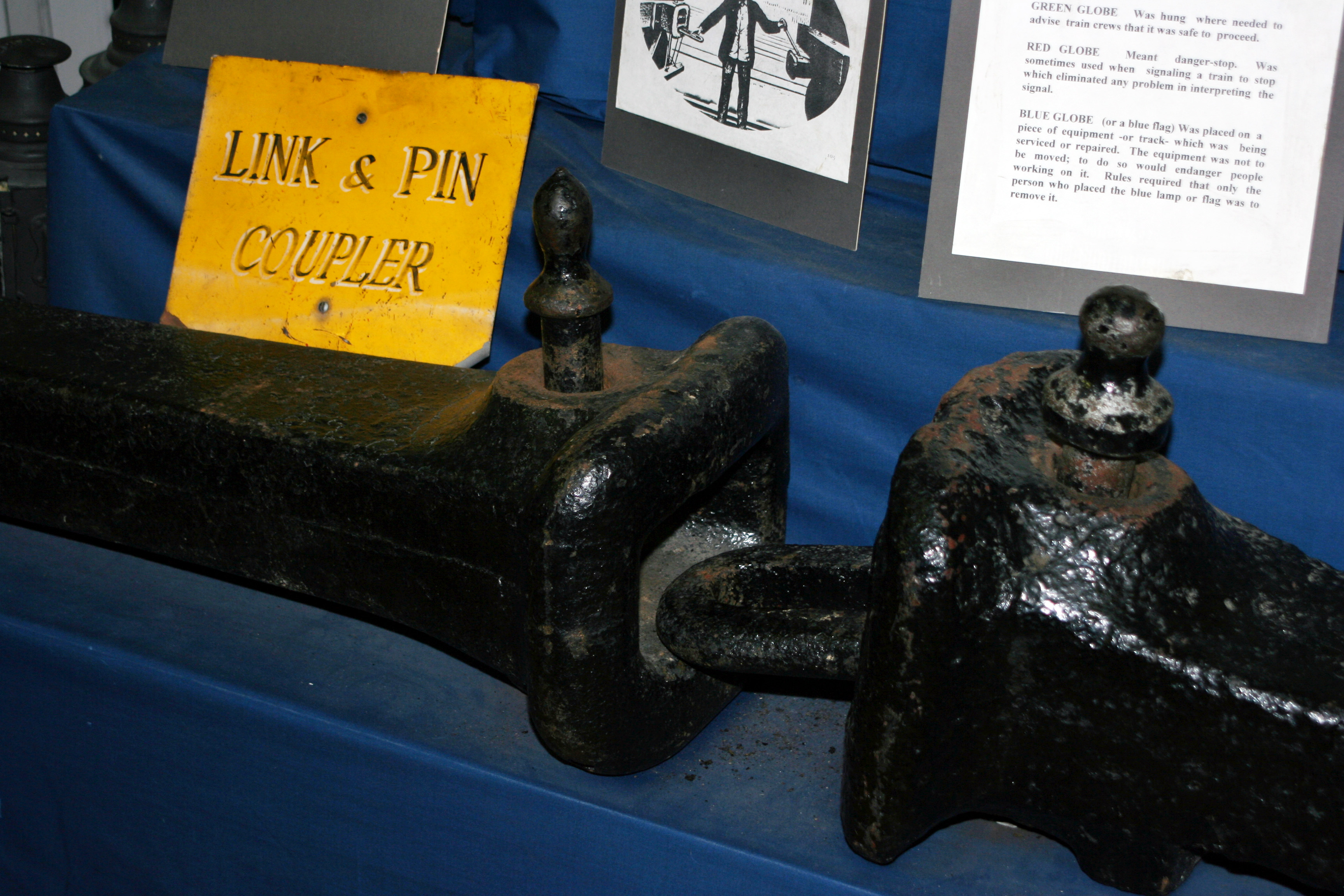
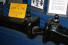 A link-and-pin coupler.
The link-and-pin coupling was the original style of coupling used on American railways, surviving on forestry railways after others converted to Janney couplings. While simple in principle, the link-and-pin coupling suffered from a lack of standardisation regarding size and height of the links and the size and height of the pockets.
The link-and-pin coupler consisted of a tubelike body that received an oblong link. During coupling, a railworker had to stand between the cars as they came together and guide the link into the coupler pocket. Once the cars were joined, the employee inserted a pin into a hole a few inches from the end of the tube to hold the link in place. This procedure was exceptionally dangerous and many brakemen lost fingers or entire hands when they did not get their hands out of the way of the coupler pockets; many more were killed as a result of being crushed between cars or dragged under cars that were coupled too quickly. Brakemen were issued with heavy clubs that could be used to hold the link in position, but many brakemen would not use the club, and risk injury.
The link-and-pin coupler proved unsatisfactory because:
- It made a loose connection between the cars, with too much slack action.
- There was no standard design, and train crews often spent hours trying to match pins and links while coupling cars.
- The links and pins were often pilfered (due to their value as scrap metal), resulting in substantial replacement costs. John H. White suggests that the railroads considered this to be more important than the safety issue at the time (see reference below).
- Crew members had to go between moving cars during coupling, and were frequently injured and sometimes killed.
- Eventually, railroads wished to operate trains that were heavier than the link-and-pin system could cope with.
An episode of the 1960s TV series Casey Jones was devoted to the problems of link-and-pin couplings.
The Miller Hook and Platform
The link and pin was replaced in U.S. passenger car usage during the latter part of the 19th century by the assemblage known as the Miller Platform, which included a new coupler called the Miller Hook. The Miller Platform (and hook coupler) was used for several decades before being replaced by the Janney coupler.
Norwegian
Main article: Norwegian coupling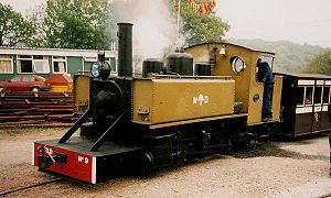
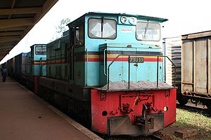 Norwegian coupling in Uganda
Norwegian (or meat chopper) couplings consist of a central buffer with a mechanical hook that drops into a slot in the central buffer. The Norwegian is found only on narrow gauge railways of 1,067 mm (3 ft 6 in) or less, such as Western Australian Government Railways, the Ffestiniog Railway and the Welsh Highland Railway, where low speeds and reduced train loads allow a simpler system. New Zealand Government Railways, during the 1970s, developed an extremely large and heavy-duty version of the chopper coupler. These were first applied to a fleet of DX class GE locomotives that had arrived from the U.S. with auto couplers, however they were converted once it was decided that these locomotives would operate on other than just the North Island Main Trunk express freight trains. On railway lines where rolling stock always points the same way, the mechanical hook may be provided only on one end of each wagon. This was the situation on the Lynton & Barnstaple (L&B), a narrow gauge line in Devon, England, and still applies to railways in New Zealand. Similarly, the hand brake handles may also be on one side of the wagons only.
Norwegian couplings are not particularly strong, and may be supplemented by auxiliary chains. The L&B originally used side chains in conjunction with Norwegian couplers, but these were found to be unnecessary with the slow speeds employed (10–15 mph/16–24 km/h) and were removed within a year or so of the line opening in 1898.
The Pichi Richi Railway in South Australia uses Norwegian couplers as its standard, and converts Janney coupler to Norwegian as required. The slot in the "buffer beam" where the coupler protrudes appears to be about the same for both types of couplers. As a museum, it is appropriate to use the older type of coupling.
Not all Norwegian couplings are compatible with one another as they vary in height, width, and may or may not be limited to one hook at a time.
Bell
See [2]
Automatic couplers
There are a number of automatic train couplings, most of which are mutually incompatible.
Janney (AAR) coupler
Main article: Janney couplerLater Master Car Builders Association[3] coupler, now AAR (Association of American Railroads) coupler; also known as knuckle coupler and alliance coupler.
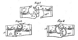 Diagram of the top view of Janney's coupler design as published in his patent application in 1873.
The knuckle coupler or Janney coupler was invented by Eli H. Janney, who received a patent in 1873 (U.S. Patent 138,405).[4] It is also known as a "buckeye coupler", notably in the United Kingdom, where some rolling stock (mostly for passenger trains) is fitted with it. Janney was a dry goods clerk and former Confederate Army officer from Alexandria, Virginia, who used his lunch hours to whittle from wood an alternative to the link and pin coupler. The term Buckeye comes from the nickname of the US state of Ohio, the "Buckeye state" and the Ohio Brass Company which originally marketed the coupling.[5][6]
In 1893, satisfied that an automatic coupler could meet the demands of commercial railroad operations and, at the same time, be manipulated safely, the United States Congress passed the Safety Appliance Act. Its success in promoting switchyard safety was stunning. Between 1877 and 1887, approximately 38% of all railworker accidents involved coupling. That percentage fell as the railroads began to replace link and pin couplers with automatic couplers. By 1902, only two years after the SAA's effective date, coupling accidents constituted only 4% of all employee accidents. Coupler-related accidents dropped from nearly 11,000 in 1892 to just over 2,000 in 1902, even though the number of railroad employees steadily increased during that decade.
When the Janney coupling was chosen to be the American standard, there were 8,000 patented alternatives to choose from. The only significant disadvantage of using the AAR (Janney) design is that sometimes the drawheads need to be manually aligned.
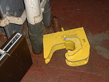
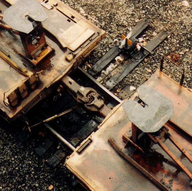
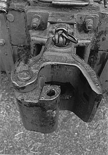 AAR Type "E" coupler serving as a tow hitch on a mobile crane. Pulling up on the link at the rear releases the knuckle allowing uncoupling.
The AAR coupler is used in Canada, the United States, Mexico, Japan, Australia, South Africa, Saudi Arabia, Cuba, Chile, Brazil, China and elsewhere. Among its features:
- Maximum tonnage as high as 32,000 metric tons (71,000,000 lb) such as on the Fortescue Railway[citation needed].
- Minimum Ultimate Tensile Strength:
- Many AAR Coupler designs exist to accommodate requirements of various car designs, but all are required to have certain dimensions in common which allow for one design to couple to any other.[9]
- Lighter weight railways, especially those of narrow gauge or with no need for Interchange (freight rail) sometimes use smaller (three-quarter- or half-size) versions of the AAR coupling.[citation needed]
- AAR couplers are always right-handed.
- Required Coupler Heights[8]
- Empty Cars: 33.5 inches (851 mm) +/- 1 inch (25 mm)
- Loaded Cars: 32.5 inches (826 mm) +/- 1-inch (25 mm)
- AAR couplers are uncoupled by lifting the coupling pin with a lever at the corner of the car. This pin is locked when the coupler is under tension, so the usual uncoupling steps are to compress the coupling with a locomotive, lift and hold up the pin, then pull the cars apart. Side operated variants are called the "Sharon coupler" or "Buckeye coupler".[6]
- Trains fitted with AAR couplers can accommodate heavier loads than any other type of coupler[citation needed]. Thus the heaviest coal trains in New Zealand have AAR couplings even though the remainder of the fleet has the "meat chopper" kind. Also, long-distance freight trains in North America are commonly more than 1-mile (1.6 km) long, whereas this is not seen in Europe[citation needed], where most freight trains still use the buffers and chain system.
Changes since 1873
 Standard AAR Type E couplers performing their function in a freight train.
The AAR coupler has withstood the test of time since its invention, and has seen only minor changes:
- The current AAR contour dates back to the Master Car Builders Association (MCBA) [3] coupler.
- Buckeye coupler, a side operated version of the MCBA coupler[6]
- Type "E" coupler, the original (plain) AAR coupler, derived from the Master Car Builders Association coupler.
- Type "F" coupler, a "tooth and socket" or "tightlock" variation to prevent accidents, derailments and wrecks from uncoupling the couplers. The "tooth" on a loose coupler could puncture any tank car or other car carrying hazardous materials. Variations on the AAR type "F" coupler have been devised to provide extra protection, in case of derailments and train wrecks, to cars routinely carrying sensitive or hazardous loads. These variations of type "F" couplers, generally involving "shelves", remain fully compatible with standard AAR couplers, but tend to keep derailments and collisions from uncoupling the cars (thereby preventing the "tooth" of the couplers from piercing the ends of the cars).
- The APTA (former AAR) standard type "H" coupler, a "tooth and socket" or "tightlock" variation used mostly, if not exclusively, on passenger cars. The Type "H" coupler is now under the supervision of the APTA (American Public Transportation Association)
- Types "F" and "H" couplers are also known as tightlock couplings.
- "pads" to reduce slack on passenger trains.
- improvement to castings, etc. to increase maximum trailing load.
- rotating-shaft couplers (type "F") introduced for use in rotary car dumpers such as on the Pilbara railways.
- narrow gauge railways such as the Victorian Puffing Billy Railway use a miniature version of the AAR coupler.
SA3 coupler
Main article: SA3 coupler The simplified scheme of the SA-3 automatic couplers.
An animation of the SA-3 couplerThe Russian SA3 coupler works according to the same principles as the AAR coupler but is incompatible,[10] it was introduced during the rebuilding of the railway network in Soviet Union after the Second World War and have since been used on the whole broad gauge network, including Finland and Mongolia. It is also used on the standard gauge networks of Iraq and on Malmbanan in Sweden for ore trains.
- Russian trains are rarely longer than about 750 m (2,460 ft)[citation needed] and rarely exceed a maximum tonnage of about 6,000 t (13,000,000 lb),[citation needed] so it is not clear what potential load these couplings are capable of. The trains on Malmbanan are about 8,000 t (18,000,000 lb).[citation needed]
- The force to break the SA-3 coupler is about 300 tonnes-force (2.9 MN; 660,000 lbf).[citation needed]
- The maximum allowed tractive effort to the SA-3 is limited to 135 tonnes-force (1.32 MN; 298,000 lbf) by Russian white papers.[citation needed]
- The proposed European automatic coupler [11] is compatible with the Russian coupler but with automatic air, control and power connections. Implementation is permanently delayed except for a few users. See Europe below.
- The SA3 resembles a left-handed fist.
Unicoupler/Intermat
Unicoupler has been developed by Knorr company from Germany in the 1970s and is widely used in Iran in freight cars. this type of coupler is compatible with SA-3 and Willison couplers. The Unicoupler is also known as AK69e. The Unicoupler was the West-European development, it was developed in parallel with a compatible East-European couterpart, the Intermat coupler.[12][13]
C-AKv
Main article: C-AKvThe C-AKv coupler is a newer compact Willison coupler developed by Faiveley Transport. It is mechanical fully compatible to the SA-3 coupler and the Unicoupler and if additional buffers are mounted it can be coupled with the conventional European screw coupling too.
Other
- Scharfenberg coupler used on electric passenger trains - connects brake and controls. See Fully Automatic Couplings below.
-
- Maximum tonnage under 1,000 t (1,100 short tons; 980 long tons).
Multi-Function Couplers
MFCs are 'fully automatic' couplers that make all connections between the rail vehicles (mechanical, air brake and electrical) without human intervention, in contrast to autocouplers which just handle the mechanical aspects. The majority of trains fitted with these types of couplers are multiple units, especially those used in mass transit operations.
There are a few designs of fully automatic couplers in use worldwide, including the Scharfenberg coupler, various knuckle hybrids (such as the Tightlock, used in the UK), the wedgelock coupling, Dellner couplings (similar to Scharfenberg couplers in appearance), BSI coupling (now Faiveley Transport) and the Schaku-Tomlinson Tightlock coupling.
There are a number of other automatic train couplings similar to the Scharfenberg coupler, but not necessarily compatible with it. Older US transit operators continue to use these non-Janney electro-pneumatic coupler designs and have used them for decades.
 Dellner manufactured Scharfenberg
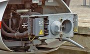 Scharfenberg
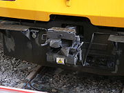 BSI (now Faiveley Transport)
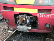 APTA, Type "H", Tightlock coupling. The connector below the coupler is not used in North America
 Wedgelock
 Budd Pin and cup coupler
Westinghouse H2C MU coupler
The Westinghouse H2C coupler is currently used on the R62, R62A, R68, R68A, R42 and R32 class subway cars of New York City Subway. The A ends of the cars typically have the Westinghouse coupler and the B ends use either a semi-permanent drawbar, or a Westinghouse coupler.
Scharfenberg coupler
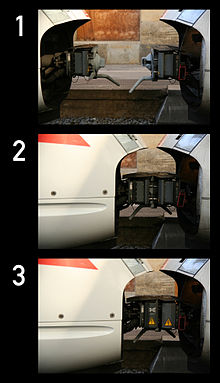 Two ICE-T trains coupling. In picture #1 both trains are ready to be coupled, picture #2 shows the trains joined mechanically, picture #3 shows the trains coupled mechanically and electrically.
The Scharfenberg coupler[14] (German: Scharfenbergkupplung or Schaku) is probably the most commonly used type of fully automatic coupling. Designed in 1903 by Karl Scharfenberg in Königsberg, Germany (today Kaliningrad, Russia), it has gradually spread from transit trains to regular passenger service trains, although outside Europe its use is generally restricted to mass transit systems. The Schaku coupler is superior in many ways to the AAR (Janney/Knuckle) coupler because it makes the electrical and also the pneumatic connections and disconnections automatic. However there is no standard for the placement of these electro-pneumatic connections. Some rail companies have them placed on the sides while others have them placed above the mechanical portion of the Schaku coupler. The main disadvantage to the Scharfenberg coupler is its low maximum tonnage, which makes it unsuitable for freight operations.
Small air cylinders, acting on the rotating heads of the coupler, ensure the Schaku coupler engagement, making it unnecessary to use shock to get a good coupling. Joining portions of a passenger train can be done at very low speed (less than 2 mph/3.2 km/h in the final approach), so that the passengers are not jostled about. Rail equipment manufacturers such as Bombardier offer the Schaku coupler as an option on their mass transit systems and their passenger cars and locomotives. In North America all the trains of the Montreal Metro are equipped with it, as are new light rail systems in Denver, Baltimore and New Jersey. It is also used on light rail vehicles in Portland, Minneapolis, the Vancouver Skytrain, and the Scarborough RT in Toronto. It also equips all the dedicated rolling stock used for the shuttle services in the Channel Tunnel.
-
- Maximum tonnage under 1,000 t (1,100 short tons; 980 long tons).
United Kingdom
Due to the rush to dieselise and electrify, the United Kingdom ended up with a variety of incompatible couplings and electrical connections. The latter were categorised as yellow triangle, blue square, and so on. This has nothing to do with the physical connection of vehicles. Coupling Codes, as they were known, only became relevant if multiple working of locomotives or Multiple Units was required.[15]
Automatic Buffing Contact Coupler
- Automatic Buffing Contact Coupler [16]
Other
Dellner [17]
Dual couplings and match wagons
 Coupling adapter for use between AAR couplers on locomotives and automatic couplers on commuter rail multiple units at New York's Pennsylvania Station. The adapter is seen from the bottom
If a wagon with one coupling system needs to be coupled to wagons with another coupling type there are two solutions. This may be needed when taking metro rolling stock from its manufacturer to the city where it is to be used:
- use a match wagon(s) which has different couplings at either end.
- use a coupling adaptor (such as illustrated).
Only some kinds of couplings coexist on the end of a wagon at the same time, because amongst other reasons they need to be at the same height. For example, in the Australian state of Victoria, engines had the AAR coupler, with buffers, and the chain mounted on a lug cast into the AAR coupler.
A match wagon or match truck (also known as a barrier vehicle / wagon in Britain and Transition Car in the United States) has different kinds of couplings at each end. If a pair of match wagons is used, a rake of wagons using coupling A can be inserted into a train otherwise using coupling B.
A coupling adaptor or compromise coupler might couple to an AAR coupling on a wagon, and present, for example, a meatchopper coupler or rapid transit coupler to the next wagon. Such an adaptor might weigh 100 kg (220 lb).
Dual coupling
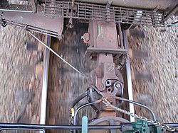
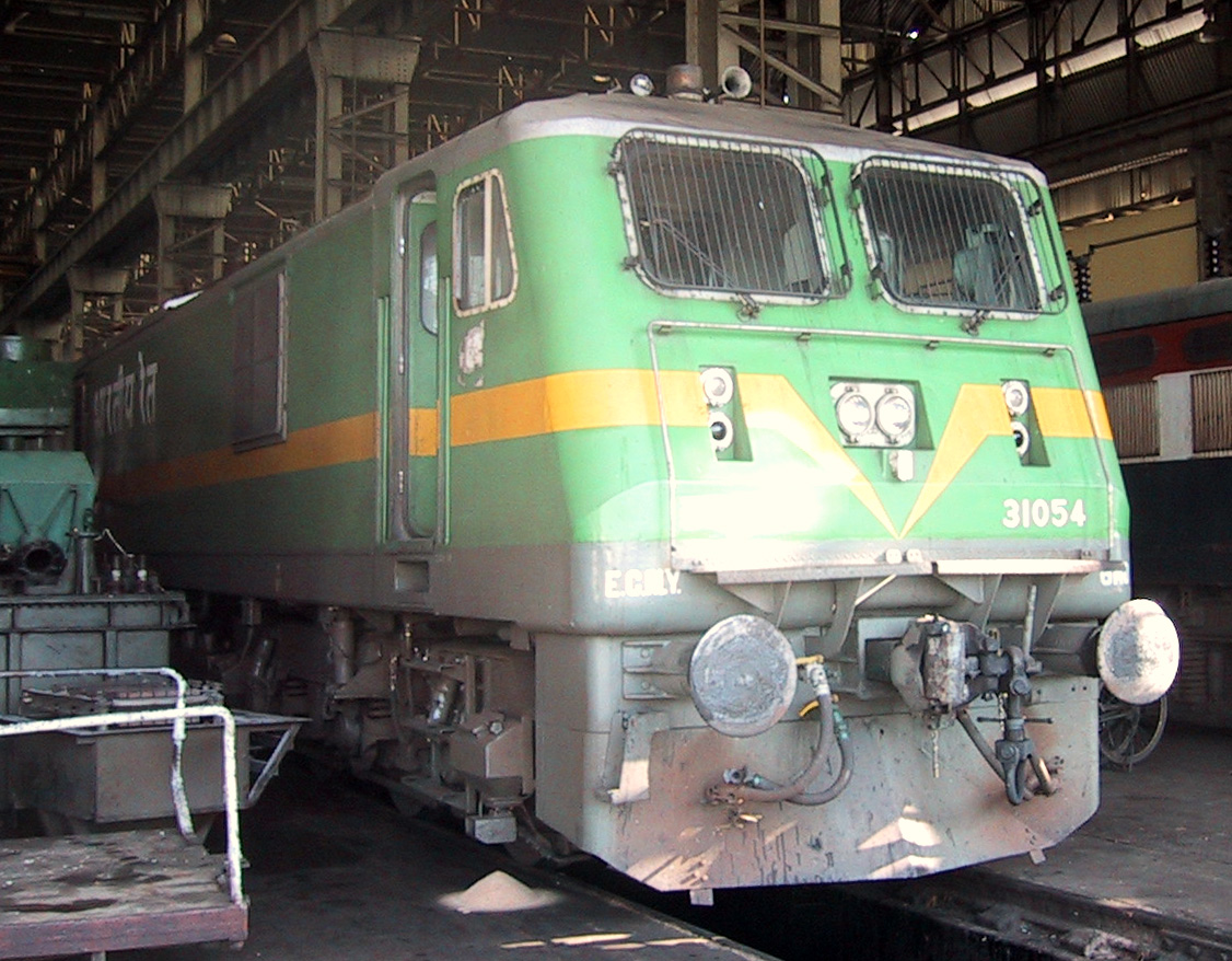
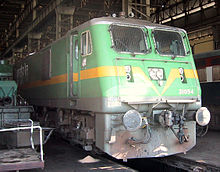 Dual coupling on a modern locomotive. (Indian locomotive class WAG-9) The chain is mounted on a hinge on the right of the coupler
It is possible to mount both buffers and chain and knuckle couplers on the same car, provided that one can swing out of the way. Alternatively, either a lug to hold the chain is cast in the body of the coupler or a chain is mounted on top of the coupler. This is also done with an SA3 coupler built by SAB WABCO.[18]
Locomotives and some freight cars of the Indian Railways are fitted with a 'transition coupler' that incorporates a screw coupling within a knuckle coupler: the knuckle coupler remains in position and does not swing away when not in use. The screw coupling is mounted on a hinge on the opposite side of the knuckle coupler. Most Indian freight cars use the knuckle coupler alone, without buffers, whereas passenger coaches almost exclusively use screw couplers and buffers. Exceptions are the new LHB coaches imported from Europe, and a few other makes of carriages converted to use knuckle couplers.[19][20]
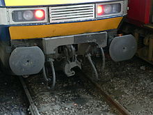
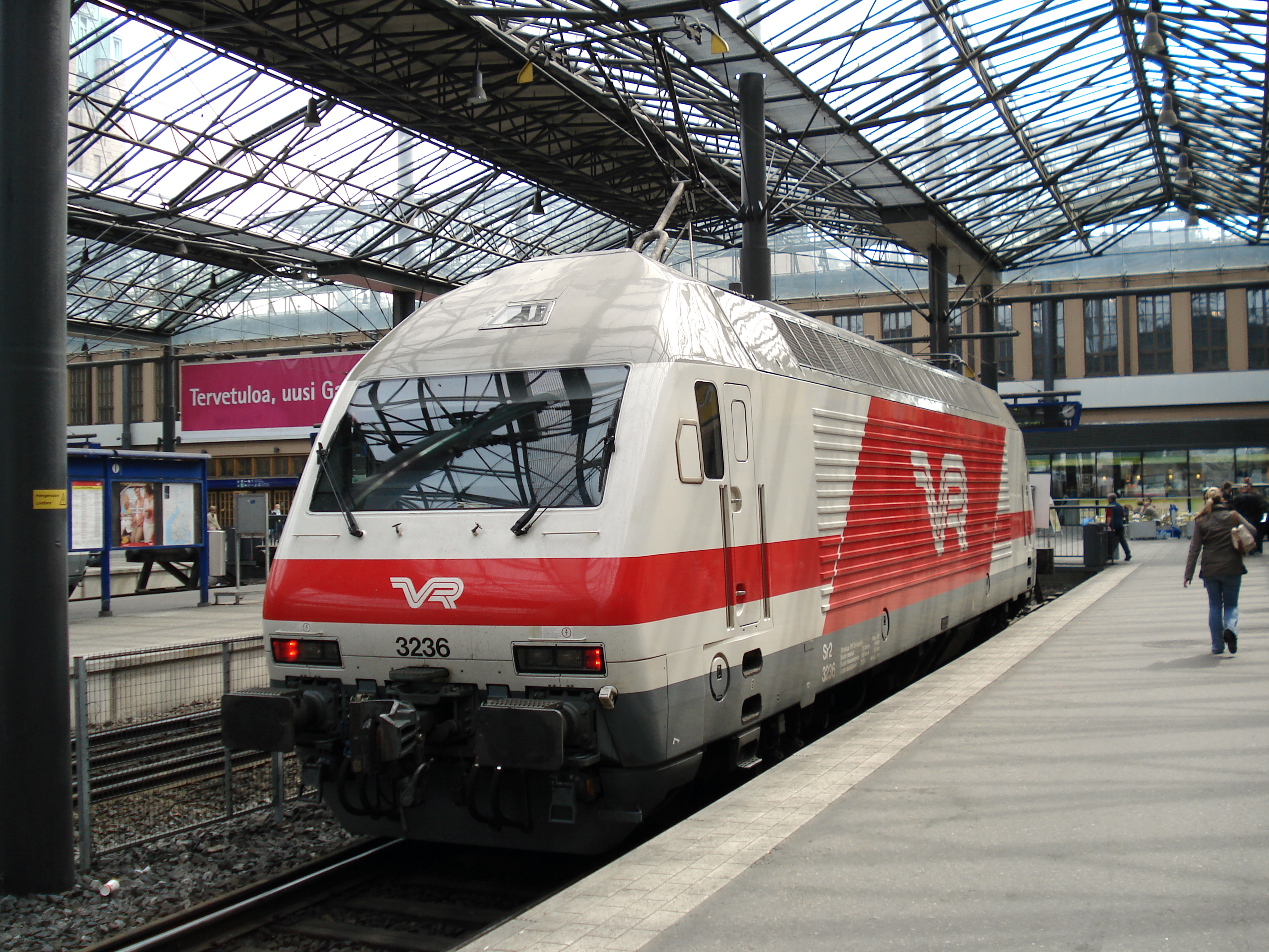
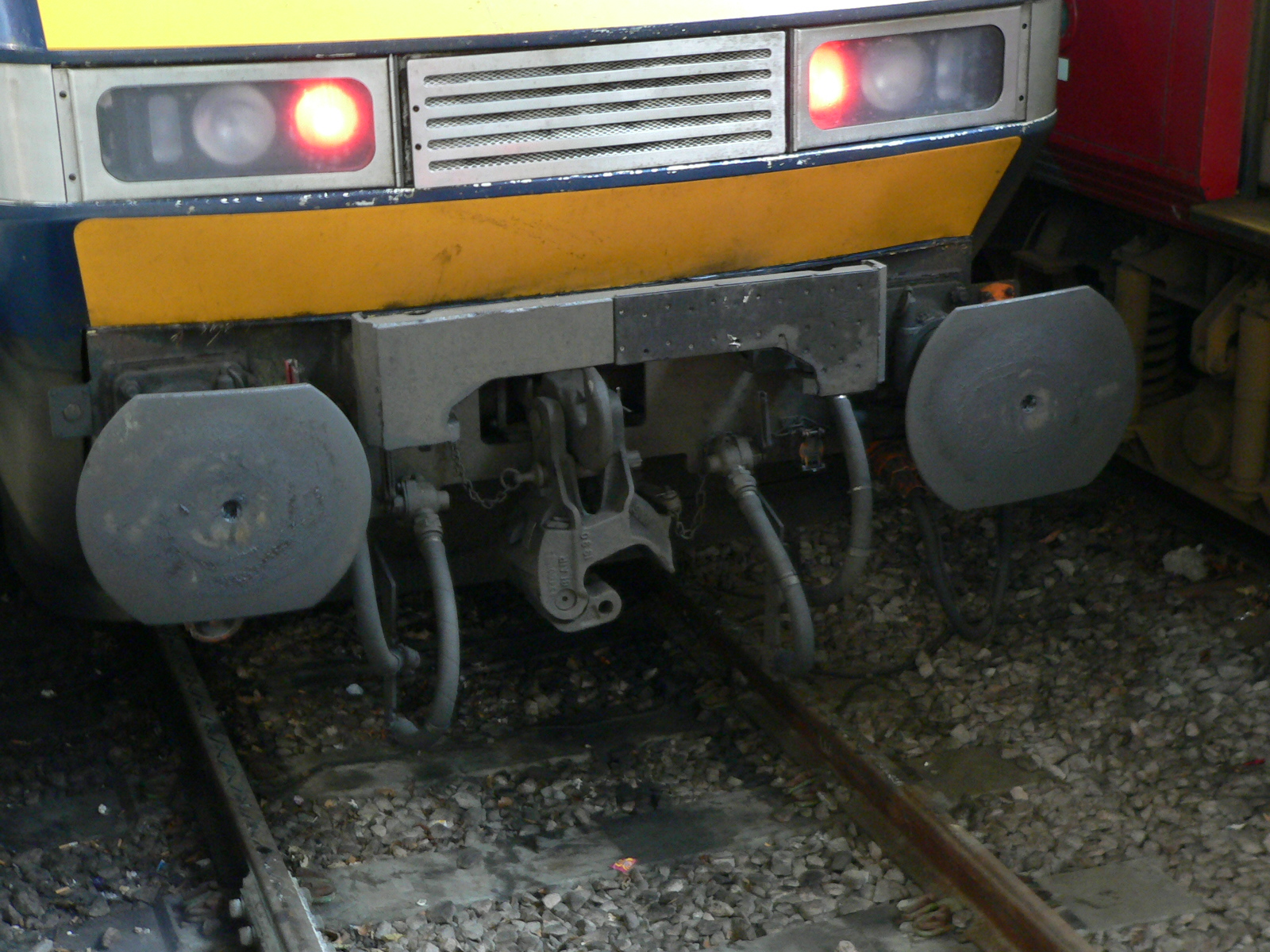
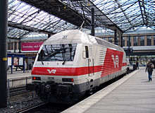 A Finnish locomotive with dual coupling
Some Russian locomotives and wagons have buffers together with the central coupler. When coupling to Finnish equipment, a short chain with a block that fits in the central coupler is placed on the Russian side, backing up and compressing the buffers so that the chain can be laid on the hook. (That is also the common way of coupling locomotives to or from wagons, faster than unscrewing the link.)
 British-style dual buffer-and-chain/automatic coupler with knuckle swung out of the way
British locomotive-hauled passenger carriages adopted a dual coupling system in the 1950s. They have retractable buffers and a central Buckeye automatic knuckle coupler that lowers to reveal a hook for a screw-type chain coupling. When in use, a pin through the buckeye shank rests in the conventional hook. No chain is provided on dual-coupled vehicles, since the chain on the other vehicle can be used when the knuckle coupler is out of the way (down). Inter-stock coupling was with the automatic coupler (with the buffers retracted), while connection to the locomotive was with the buffer-and-chain system with a screw coupler. Today this dual coupling system has been adopted for all loco-hauled passenger trains in Great Britain to allow faster shunting operations.
If worst comes to worst one might use a rope to join two wagons together, as might happen if one of the couplers breaks in service. This formed a plot point in the British comedy film The Titfield Thunderbolt, where a rope had to be used to connect a commandeered antique locomotive to its train. The rope subsequently snapped, leaving the train stranded.
Sets of carriages
Automatic couplers like the Janney are safer in a collision because they help prevent the carriages telescoping. British Rail therefore decided to adopt a Janney variant for its passenger carriages, with the coupler able to swing out of the way for coupling to engines with the traditional buffer and chain system.
In New South Wales, sets of carriages were permanently coupled with a fixed bar, since the carriages were disconnected only at the workshops. Freight cars are sometimes coupled in pairs or triplets, using bar couplings in between.
Articulated sets of carriages or wagons share the intermediate bogies, and have no need for couplings in the intermediate positions.
Coupler conversion
From time to time, a railway decides that it needs to upgrade its coupling system from one that is proving unsatisfactory, to another that meets future requirements. This can be done gradually, which can create lots of problems with transitional incompatibilities, or overnight, which requires a lot of planning.
Japan
Japan converted its British-derived buffer and chain couplings to the American Janney coupling over a period of a few days in the early 1920s, after considerable preparation. Today, most (if not all) EMUs including high-speed Shinkansen trains, and some DMUs use the Shaku-Thomlinson type coupling system, while locomotive-hauled trains use the Janney coupling and Tightlock coupling system.
Australia
Australia, with its breaks of gauge, has always had different couplers on different systems, and has generally adopted gradual conversion. Conversion to the Janney coupling is now virtually complete. Commonwealth Railways started with Janney couplings on its standard gauge Trans-Australian line, and some railways, like the former Victorian Railways and the Queensland Railways, used dual couplers. Older couplers remain on Heritage railways.
Europe
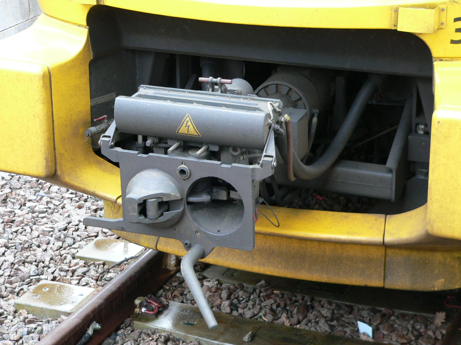
The European network has traditionally been formed of many independent national railway networks with buffer and chain used near universally to allow the interchange of rolling stock. The European Union Technical Specifications for Interoperability (TSIs) for high-speed passenger rolling stock mandate the use of Scharfenberg Type 10-compatible couplings. The Type 10 includes "horns" to aid coupling on curves and include a function to provide standardised automatic air-brake connections; the coupling horn is often visible poking out at the front of the nose of high-speed trains.
For European freight, the TSIs mandate buffer and chain couplings at specified heights. The European system links to the former Soviet Russian-gauge network, where SA3 automatic couplers are used. Some research has been undertaken to chose an automatic freight coupler compatible with the Soviet one, but owing to widescale replacement cost, no action has been taken to implement the conversion, except for some trial installations. In many heavy-haul applications, such as for coal and iron ore, either US AAR-type couplers or Soviet SA-3 couplers are used. Conversion is made harder to justify because the existing buffer and chain coupling is almost universal.
Meanwhile, drawgear of new rolling stock is being built at a height suitable for conversion. The proposed European freight coupling is compatible with the SA3 coupler but adds integrated air and electrical connections. This standard would need to be revised to allow for the unforeseen development of electronically controlled pneumatic brakes.
United States
Once Congress passed the Safety Appliance Act mandating conversion from the link and pin coupler to the Janney coupler, railroads in the United States had only a few years to implement the change. The railroads in North America, except for mass transit, form one unitary system, and uniformity of couplers is important for smooth interchange of rolling stock.
Latin America
Railways in Central and South America are fragmented by gauge, geography, and financial and technical heritage. While some systems have adopted the American Janney coupler, others retain the British buffer and hook (buffer and chain) coupler (see above).
Soviet Union and successor states
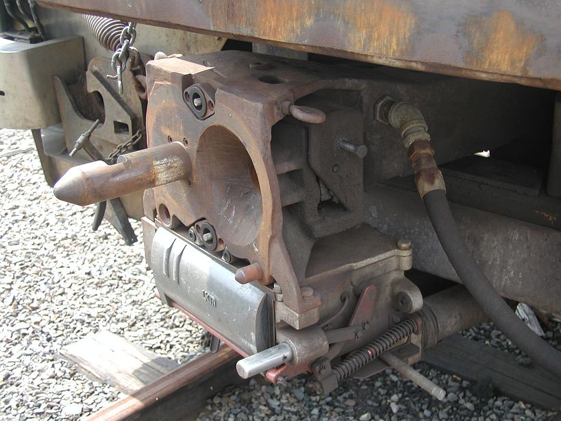
 Detail of the SA-3 coupler in coupled mode
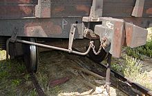 SA-3 coupler, uncoupled
Russian Empire and later Soviet Union used buffer and chain couplings, albeit with possibly wider centres for the buffers, until conversion to automatic SA3 couplers. The SA3 coupler was invented in 1932. Some wagons were equipped with SA-3 couplers in the 1930s (they could be coupled with chain coupling), but all cars received automatic couplers in 1957.[21][22]
Middle East
While the Middle East is mostly standard gauge, three different couplings appear to be in use (not counting Scharfenberg couplings on EMU trains). These are buffer-and-chain, American, and Russian types.
Africa
South of the Sahara, Janney (AAR) and chopper couplings (not necessarily of compatible types) appear to account for most couplings. The preferred and proposed UAR standard is the American Janney (AAR) coupling.
- Rail transport in Ghana [23]
Brake couplings
Main article: Brake (railway)Couplings are needed for any continuous braking systems.
Drawgear
Drawgear is structure that links the couplings at each end of the waggon to provide the strength needed to form trains. Early drawgear was make of wood, gradually being replaced by steel.
Combined buffer-couplings have a centre sill to take the forces.
Buffers and chains tend to have the two buffers spaced according to the gauge.
Electronically controlled brakes
Electronically controlled pneumatic brakes (ECP) need a method of connecting electrically adjacent wagons, both for power and for command signals, and this can be done by plugs and sockets, or by very short range radio signals.
Model trains
On model railroads couplers vary according to scale, and have evolved over many years. Early model trains were coupled using various hook-and-loop arrangements, which were frequently asymmetrical, requiring all cars to be pointing in the same direction. In the larger scales, working scale or near-scale models of Janney couplers were quite common, but proved impractical in HO and smaller scales.
For many years, the "X2F" or "Horn-Hook" coupler was quite common in HO scale, as it could be produced as a single piece of moulded plastic. Similarly, for many years, a "lift-hook" coupler known as the Rapido and developed by Arnold, a German manufacturer of N-scale model trains, was commonly used in that scale.
The chief competitor of both these couplers, more popular among serious modellers, was the Magne-Matic, a magnetically-released knuckle coupler developed by Keith and Dale Edwards, and manufactured by Kadee, a company they started. While they closely resemble miniature Janney couplers, they are somewhat different mechanically, with the knuckle pivoting from the center of the coupler head, rather than from the side. A steel pin, designed to resemble an air brake hose, allows the couplers to be released magnetically; the design of the coupler head prevents this from happening unless the train is stopped or reversed with a mated pair of couplers directly over an uncoupling magnet. An earlier, mechanically-tripped version of the design had a straight pin extending down from the knuckle itself, which engaged a diamond-shaped mechanical "ramp" between the rails, which had to be raised above rail height when uncoupling was desired.
Once the Kadee patents ran out, a number of other manufacturers began to manufacture similar (and compatible) magnetic knuckle couplers.
Recently, an exact-scale HO model of the AAR coupler has been designed and manufactured by Frank Sergent, of Sergent Engineering. This design uses a tiny stainless steel ball to lock the knuckle closed. Uncoupling is achieved by holding a magnetic wand over the coupler pair to draw the balls out of the locking pockets.
In O scale, an exact-scale working miniature version of the "Alliance" coupler was manufactured from the 1980s by GAGO models in Australia. Since 2002 it has been marketed by the Waratah Model Railway Company European modellers tend to use scale hook and chain couplings.
In British 00 scale (similar to H0 scale) models the 'tension lock' coupler developed by Tri-ang is standard. This is similar in operation to the meatchopper type of coupling. Remote uncoupling is possible by using a sprung ramp between the rails. By halting the train over the ramp, it is split at this point. While it works well, it is often seen as ugly and obtrusive (although smaller designs are available, these are not always fully compatible with other models) and many British modellers prefer to retrofit either Kadee types or working hook and chain couplings.
A recent development is an interchangeable coupling which plugs into a standardised socket, known as NEM 362 and which can be easily unplugged as required. This allows the modeller to easily standardise on whatever coupling is desired, without individual manufacturers needing to change their coupling type.
For a comparison of coupler types see [24]
Accidents
Different kinds of coupling have different accident rates.
- UK 1906 - twelve fatal and 523 non-fatal accidents [25]
- The Murulla rail accident of 1926 involved the breakage of a "drawhook" leading to a runaway and then a collision. Drawhooks imply "buffers and screw" couplings.
- Round Oak - 1858 - coupling broke and rear of train rolled back.
See also
- Corridor connection
- Coupling (railway) by country
- Buckeye Steel Castings
- South Station (Boston), includes a sculpture built of railroad car couplers
References
- ^ Steam Spirit, Vol 1, p129
- ^ http://www.worldrailfans.info/forum/viewtopic.php?t=1727&highlight=sa3couplers
- ^ a b MCB
- ^ Eli Janney — The Janney Coupler
- ^ [1]
- ^ a b c Buckeye coupler (scroll down)
- ^ a b AAR Manual of Standards and Recommended Practices, Section S, Part I:Casting Details, Issue 06/2007
- ^ a b AAR 2011 Field Manual
- ^ AAR Manual of Standards and Recommended Practices, Section S, Part III:Coupler and Yoke Details, Issue 06/2007
- ^ Animation showing SA3 coupling (site in Russian)
- ^ European proposal coupler
- ^ Index
- ^ History
- ^ Scharfenberg coupler
- ^ Modern Railways October 2008, p62
- ^ ABC Couplers
- ^ Dellner Couplers AB — Automatic and Semi-Permanent Couplers
- ^ SAB WABCO C-AK
- ^ Coupler conversion
- ^ Centre Buffer Coupler of AAR type
- ^ Intermat/Willison coupler
- ^ ru:Автосцепка СА-3 (in Russian)
- ^ Ghana
- ^ "An introduction to Couplers", Model Railways in Australia (magazine), issue 3, 2009
- ^ Hansard
Sources
- Norfolk & Western Railway Co. v. Hiles (95-6), 516 U.S. 400 (1996) (U.S. Supreme Court decision by Justice Clarence Thomas)
- Eli Janney — The Janney Coupler (based on above case)
- Dellner Couplers AB — Automatic and Semi-Permanent Couplers
- Vancouver SkyTrain Light Rail Network, Canada (these two for Dellner data)
- JANE'S WORLD RAILWAYS
- How couplings work
- White, John H. Jr, The American Railroad Passenger Car (1978), Chapter 7. ISBN 0-8018-1965-2 (hardcover), ISBN 0-8018-2743-4 (paperback, two-volume set—Chapter 7 is in Volume 2)
External links
- West Somerset Railway - Feature: Couplings – Descriptions of: three-link, Instanter, Screw, Buckeye
- ASF Keystone, Inc.[dead link]
- A history of the automatic coupler
- Janney Coupler
- A.B.C. Coupler Ltd.
- McConway & Torley Group
- Dellner Couplers Group
- Scharfenberg couplers
- Braithwaite (India) couplers
- Stäubli couplings
- Image of a Tomlinson coupler
- Intermat/Willison coupler
- Willison
- Setesdalsbanen - Many picture of Norwegian (chopper) coupler)
- (Russian) Animation showing SA3 coupling
- Egyptian loco with CBC and buffers removed
- Egyptian loco with buffers and screw coupling H*D signal
- Knorr-Bremse Unicoupler
- Unicoupler text
Categories:- Rail technologies
- Locomotive parts
- Couplers
- Standard gauge - England


Wikimedia Foundation. 2010.