- Rail profile
-
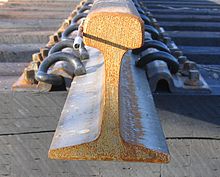
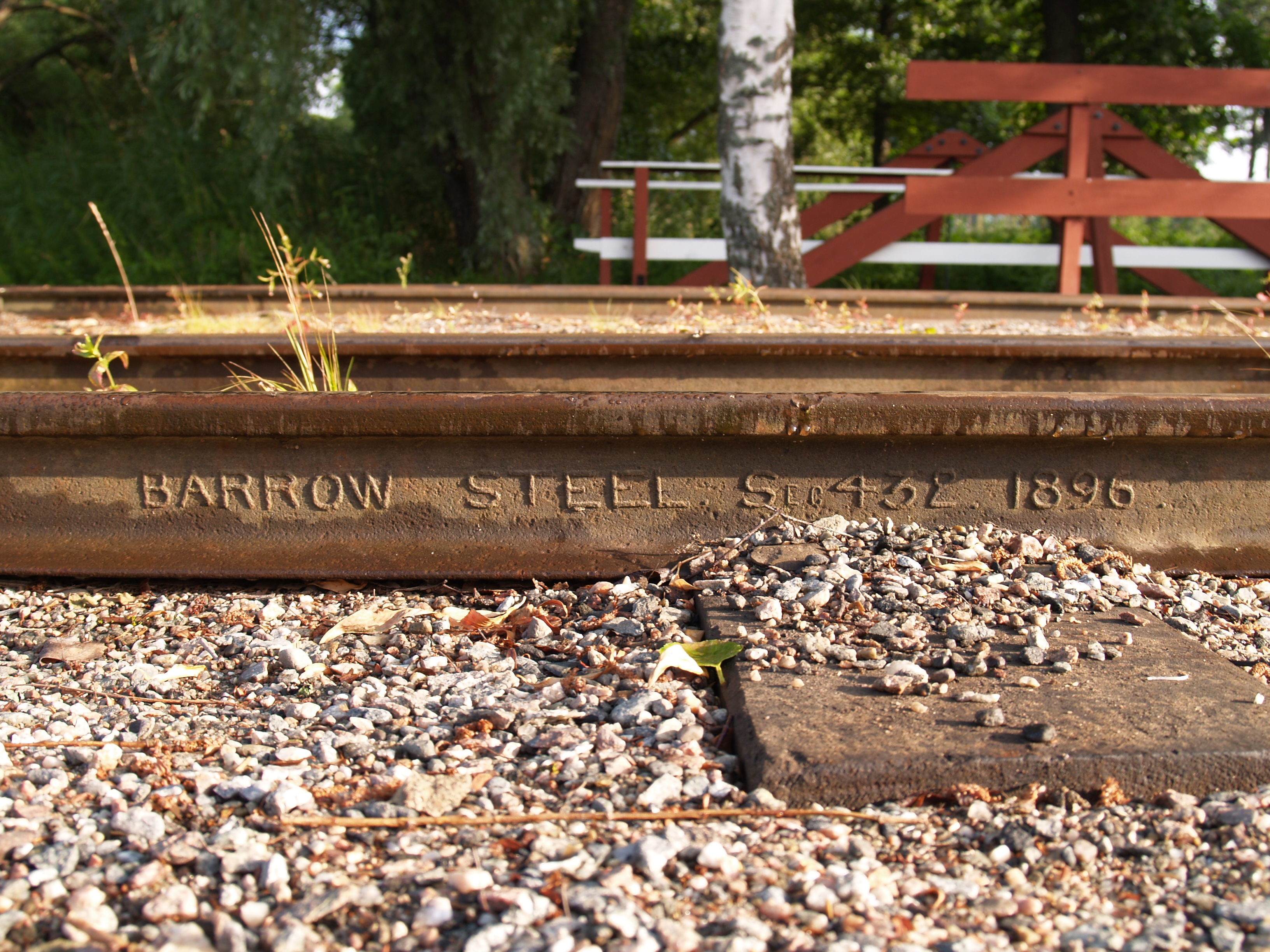
 Rail from 1896
 Cross-sections of flat-bottomed which can rest directly on the sleepers, and bullhead rails which sit in chairs (not shown).
The rail profile is the cross sectional shape of a railway rail,[1] perpendicular to the length of the rail.
In all but very early cast iron rails, a rail is hot rolled steel (once wrought iron) of a specific cross sectional profile (an asymmetrical I-beam) designed for use as the fundamental component of railway track.
Unlike some other uses of iron and steel, railway rails are subject to very high stresses and have to be made of very high quality steel. It took many decades to improve the quality of the materials, including the change from iron to steel. Minor flaws in the steel that pose no problems in reinforcing rods for buildings can, however, lead to broken rails and dangerous derailments when used on railway tracks.
By and large, the heavier the rails and the rest of the trackwork, the heavier and faster the trains these tracks can carry.
The rails represent a substantial fraction of the cost of a railway line. Only a small number of rail sizes are made by steelworks at one time, so a railway must choose the nearest suitable size. Worn, heavy rail from a mainline is often reclaimed and downgraded for re-use on a branchline, siding or yard.
Contents
Rail weights and sizes
 Two commonly used rail profiles: a heavily worn 50 kg-profile and a new 60 kg-profile
The weight of a rail per length is an important factor in determining rails strength and hence axleloads and speeds.
Weights are measured in pounds per yard or kilograms per metre; the pounds-per-yard figure is almost exactly double the kilograms-per-metre figure. Rails in Canada, the United Kingdom and United States are still described using imperial units. In Australia, metric units are now used as in mainland Europe.
In rail terminology Pound is used synonymously with pounds per yard, e.g. a 132 pound rail means a rail of 132 lb/yd.
Europe
Rails are made in a large number of different sizes. Some common European rail sizes include:
- 40 kg/m (80.6 lb/yd)
- 50 kg/m (100.8 lb/yd)
- 54 kg/m (108.9 lb/yd)
- 56 kg/m (112.9 lb/yd)
- 60 kg/m (121 lb/yd)
In the countries of former USSR 65 kg/m (131 lb/yd) rails and 75 kg/m (151.2 lb/yd) rails (not thermally hardened) are common. Thermally hardened 75 kg/m (151.2 lb/yd) rails also have been used on heavy-duty railroads like Baikal-Amur Mainline, but have proven themselves deficient in operation and were mainly rejected in favor of 65 kg/m (131 lb/yd) rails.[2]
North America
 Weight mark on a jointed segment of 155 lb/yd (76.9 kg/m) "Pennsylvania Special" rail, the heaviest grade of rail ever mass produced
The American Society of Civil Engineers (or ASCE) specified rail profiles in 1893 for 5-pound-per-yard (2.48 kg/m) increments from 40 to 100 pounds per yard (19.8 to 49.6 kg/m). Height of rail equaled width of foot for each ASCE tee-rail weight; and the profiles specified fixed proportion of weight in head, web and foot of 42%, 21% and 37%, respectively. ASCE 90 lb/yd (44.6 kg/m) profile was adequate; but heavier weights were less satisfactory. In 1909 the American Railway Association (or ARA) specified standard profiles for 10 lb/yd (4.96 kg/m) increments from 60 to 100 lb/yd (29.8 to 49.6 kg/m). The American Railway Engineering Association (or AREA) specified standard profiles for 100 lb/yd (49.6 kg/m), 110 lb/yd (54.6 kg/m) and 120 lb/yd (59.5 kg/m) rails in 1919, for 130 lb/yd (64.5 kg/m) and 140 lb/yd (69.4 kg/m) rails in 1920, and for 150 lb/yd (74.4 kg/m) rails in 1924. The trend was to increase rail height/foot-width ratio and strengthen the web. Disadvantages of the narrower foot were overcome through use of tie-plates. AREA recommendations reduced the relative weight of rail head down to 36%, while alternative profiles reduced head weight to 33% in heavier weight rails. Attention was also focused on improved fillet radii to reduce stress concentration at the web junction with the head. AREA recommended the ARA 90 lb/yd (44.6 kg/m) profile.[3] Old ASCE rails of lighter weight remained in use, and satisfied the limited demand for light rail for a few decades. AREA merged into the American Railway Engineering and Maintenance-of-Way Association in 1997. By the mid-20th century, most rail production was medium heavy (112 to 119 lb/yd/55.6 to 59.0 kg/m) and heavy (127 to 140 lb/yd/63.0 to 69.4 kg/m) Sizes under 100 lb/yd (49.6 kg/m) rail are usually for lighter duty freight, low use trackage, or light rail. Track using (100 to 120 lb/yd (49.6 to 59.5 kg/m)) rail is for lower speed freight branch lines or rapid transit (for example, most of the New York City Subway system track is constructed with 100 lb/yd (49.6 kg/m) rail). Main line track is usually built with 130 lb/yd (64.5 kg/m) rail or heavier. Some common North American rail sizes include:[4]
- 75 lb/yd (37.2 kg/m) (ASCE)
- 85 lb/yd (42.2 kg/m) (ASCE)
- 90 lb/yd (44.6 kg/m) (ARA)
- 100 lb/yd (49.6 kg/m) (AREA)
- 105 lb/yd (52.1 kg/m) New York Central Railroad
- 115 lb/yd (57.0 kg/m) (AREA)
- 119 lb/yd (59.0 kg/m) Colorado Fuel and Iron
- 127 lb/yd (63.0 kg/m) New York Central Railroad
- 132 lb/yd (65.5 kg/m) (AREA)
- 133 lb/yd (66.0 kg/m) (AREA)
- 136 lb/yd (67.5 kg/m) Colorado Fuel and Iron
- 140 lb/yd (69.4 kg/m) (AREA)
- 141 lb/yd (69.9 kg/m) (produced by Nippon (Japan))
- 155 lb/yd (76.9 kg/m) (no longer production) Pennsylvania Railroad
Some common North American crane rail sizes include:
- 12 lb/yd (5.95 kg/m)
- 20 lb/yd (9.9 kg/m)
- 25 lb/yd (12.4 kg/m)
- 30 lb/yd (14.9 kg/m)
- 40 lb/yd (19.8 kg/m)
- 60 lb/yd (29.8 kg/m)
- 80 lb/yd (39.7 kg/m)
- 85 lb/yd (42.2 kg/m)
- 104 lb/yd (51.6 kg/m)
- 105 lb/yd (52.1 kg/m)
- 135 lb/yd (67 kg/m)
- 171 lb/yd (84.8 kg/m)
- 175 lb/yd (86.8 kg/m)
Australia
Some common Australian rail sizes include:
- 30 kg/m (60.5 lb/yd)
- 36 kg/m (72.6 lb/yd)
- 40 kg/m (80.6 lb/yd)
- 47 kg/m (94.7 lb/yd)
- 50 kg/m (100.8 lb/yd)
- 53 kg/m (106.8 lb/yd)
- 60 kg/m (121 lb/yd)
- 68 kg/m (137.1 lb/yd) (no longer production)
- 50 kg and 60 kg are the current standard, although some other sizes are still manufactured.[5]
- Some American sizes are used on northwest Western Australian iron ore railways.
History
 Fishbelly edge rails laid on stone blocks
 Cross sections of early rails
Early rails were used on horse drawn wagonways, originally with wooden rails,[6] but from the 1760s using strap-iron rails, which consisted of thin strips of cast iron fixed onto wooden rails.[7] These rails were too fragile to carry heavy loads, but because the initial construction cost was less, this method was sometimes used to quickly build an inexpensive rail line. Strap rails sometimes separated from the wooden base and speared into the floor of the carriages above, creating what was referred to as a "snake head." However, the long-term expense involved in frequent maintenance outweighed any savings.[8][9]
These were superseded by cast iron rails which were flanged (i.e. 'L' shaped) with the wagon wheels being flat, an early exponent being Benjamin Outram. His partner William Jessop had pioneered the use of "edge rails" in 1789 where the wheels were flanged and, over time it was realised that these worked better.
The earliest of these in general use were the so-called cast iron fishbelly rails from their shape. Rails made from cast iron were brittle and broke easily. They could only be made in short lengths which would soon become uneven. John Birkinshaw's 1820 patent,[10] as rolling techniques improved, introduced wrought iron in longer lengths, replaced cast iron and contributed significantly to the explosive growth of railroads in the period 1825-40. The cross-section varied widely from one line to another, but were of three basic types as shown in the diagram. The parallel cross-section which developed in later years was referred to as Bullhead.
Meanwhile, in May 1831, the first flanged T rail (also called T-section) arrived in America from Britain and was laid into the Pennsylvania Railroad by Camden and Amboy Railroad. They were also used by Charles Vignoles in Britain.
The first steel rails were made in 1857 by Robert Forester Mushet, who laid them at Derby station in England.[11] Steel is a much stronger material, which steadily replaced iron for use on railway rail and allowed much longer lengths of rails to be rolled.
The American Railway Engineering Association (AREA) and the American Society for Testing Materials (ASTM) specified carbon, manganese, silicon and phosphorus content for steel rails. Tensile strength increases with carbon content, while ductility decreases. AREA and ASTM specified 0.55 to 0.77 percent carbon in 70-to-90-pound-per-yard (35 to 45 kg/m) rail, 0.67 to 0.80 percent in rail weights from 90 to 120 pounds per yard (45 to 60 kg/m), and 0.69 to 0.82 percent for heavier rails. Manganese increases strength and resistance to abrasion. AREA and ASTM specified 0.6 to 0.9 percent manganese in 70 to 90 pound rail and 0.7 to 1 percent in heavier rails. Silicon is preferentially oxidised by oxygen and is added to reduce the formation of weakening metal oxides in the rail rolling and casting procedures.[12] AREA and ASTM specified 0.1 to 0.23 percent silicon. Phosphorus and sulfur are impurities causing brittle rail with reduced impact-resistance. AREA and ASTM specified maximum phosphorus concentration of 0.04 percent.[13]
The use of welded rather than jointed track began in around the 1940s and had become widespread by the 1960s.
Types
Flanged rail
Flanged rail was an early type of rail and had an 'L' cross section in which the flange kept an unflanged wheel on the track. The flanged rail has seen a minor revival as the Guided bus. In the Cambridgeshire guided busway the rail is a 350 mm thick concrete beam with a 180 mm lip to form the flange. The buses run on normal road wheels with side mounted guidewheels to run against the flanges. Buses are steered normally when off the busway, analogous to the 18th C wagons which could be manouvered around pitheads before joining the track for the longer haul.
Baulk rail
Main article: Baulk roadBaulk road was an early type of longitudinally supported rail, pioneered by Isambard Kingdom Brunel.
Barlow rail
 Cross section of Barlow rail as used by Sydney Railway CompanyMain article: Barlow rail
Barlow rail was invented by William Henry Barlow in 1849. It was designed to be laid straight onto the ballast, but the lack of sleepers meant that it was difficult to keep it in gauge.
Vignoles rail
 Vignoles Rail as used for the London and Croydon Railway in 1839
 Vignoles rail as used for the Birmingham and Gloucester Railway in 1840
Vignoles rail is the popular name of the flat-bottomed rail used internationally for railway track, recognising engineer Charles Vignoles who introduced it to Britain.
Flat bottomed rail was first introduced in America by R.L.Stevens in 1830. There were no steel mills in America capable of rolling long lengths, so it was manufactured in Britain. Charles Vignoles observed that wear was occurring with steel rails and steel chairs upon stone blocks, the normal system at that time. In 1836 he recommended flat-bottomed rail to the London and Croydon Railway for which he was consulting engineer.
His original rail had a smaller cross-section to the Stevens rail, with a wider base than modern rail, fastened with screws through the base. Other lines which adopted it were the Hull and Selby, the Newcastle and North Shields, and the Manchester, Bolton and Bury Canal Navigation and Railway Company. [14]
When it became possible to preserve wooden sleepers with mercuric chloride (a process called Kyanising) and creosote, they gave a much quieter ride than stone blocks and it was possible to fasten the rails directly using clips or rail spikes. Their use spread worldwide and acquired Vignoles' name.
Flanged T rail
 Cross section of new flanged T rail
Iron-strapped wooden rails were used on all American railways until 1831. Col. Robert L. Stevens, the President of the Camden and Amboy Railroad, conceived the idea that an all-iron rail would be better suited for building a railroad. He sailed to England which was the only place where his flanged T rail (also called T-section) could be rolled. Railways in England had been using rolled rail of other cross-sections which the ironmasters had produced.
In May, 1831, the first 500 rails, each 15 feet (4.57 m) long and weighing 36 pounds per yard (17.9 kg/m), reached Philadelphia and were placed in the track, marking the first use of the flanged T rail. Afterwards, the flanged T rail became employed by all railroads in the United States. Col. Stevens also invented the hooked spike for attaching the rail to the crosstie (or sleeper). At the present time, the screw spike is being used widely in place of the hooked spike.
The joint where two rails are connected is the weakest part of a rail line. The earliest iron rails were joined by a simple fishplate or bar of metal bolted through the web of the rail. Stronger methods of joining two rails together have been developed. When sufficient metal is put into the rail joint, the joint is almost as strong as the rest of the rail length. The noise generated by trains passing over the rail joints, described as "the clickity clack of the railroad track", can be eliminated by welding the rail sections together forming a continuous rail. One kind of welding is the Thermite welding process.
Double-headed rail
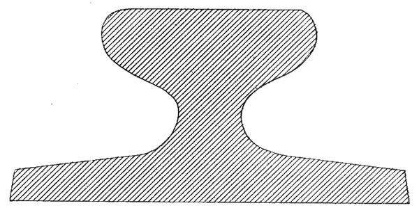
In late 1830s England, railway lines had a vast range of different patterns. One of the earliest lines to use double-headed rail was the London and Birmingham Railway, which had offered a prize for the best design. This rail was supported by chairs and the head and foot of the rail had the same profile. The supposed advantage was that, when the head became worn, the rail could be turned over and re-used. In practice, this form of recycling was not very successful as the chair caused dents in the lower surface, and double-headed rail evolved into bullhead rail in which the head was more substantial than the foot.
Bullhead rail
 A lot of steel shaved away; tips are weak and straight leading to slow speeds on turnout.
Bullhead rail is similar to double-headed rail but with a heavier profile to the top edge. It became the standard for the British railway system until the mid-20th century but has now been largely replaced by flat-bottom rail. Bullhead rail is still used on the London Underground and survives on the national rail system in some sidings or branch lines. One of the first British Standards, BS 9, was for bullhead rail - it was originally published in 1905, and revised in 1924. Rails manufactured to the 1905 standard were referred to as "O.B.S." (Original), and those manufactured to the 1924 standard as "R.B.S." (Revised).[15]
Tangential turnouts
 Not so much steel shaved away; tips are strong allowing curved turnouts and higher speeds. Tangential switch (green) rests on chair that is higher.
Old style turnouts use the same section rail for both stock rail and switch rail. A lot of steel has to be "filed" away, and the point tends to be thin and weak. To minimise the weak part, the switches are straight and form a coarse angle, which gives trains a jolt.
Tangential turnouts are made using two different rail profiles, the normal flat bottom rail for the stock rails, and a lower height and stockier profile for the switches. The difference in height of these two profiles is about 25mm, but as the switch rail rests on a base plate 25mm taller, both rails present themselves at the same height to the wheels.
The tangential switch rail has less steel filed away, and the mid part of the switch "scallops" into the web of the stock rail for greater strength. The higher baseplate also supports the switch rail better. The stronger switch allows that switch to be curved, reducing any jolt to the train and allowing higher speeds.
Tangential turnouts still lack a transition at the switch, so there is still a jolt at the switch, but much smaller jolt than with the old style turnouts.
The weight of the two types of rail is about the same.
Grooved rail
-
 Cross section of a grooved tram rail
See also: Grooved rail
A grooved rail, groove rail, or girder rail is a special grooved rail designed for tramway or railway track in pavement or grassed surfaces (grassed track or track in a lawn). This was invented in 1852 by Alphonse Loubat, a French inventor who developed improvements in tram and rail equipment, and helped develop tram lines in New York City and Paris. The invention of grooved rail enabled tramways to be laid without causing a nuisance to other road users, except unsuspecting cyclists, who could get their wheels caught in the groove.
The groove needs to be cleaned of gravel and dirt, otherwise the flange on the wheel may be derailed, a problem which also affects the LR55 rail below.
LR55 rail
- See also:Other tram track profiles
 LR55 cross section
LR55 rail is a special rail section, designed for use in embedded tramway track installations. It is a top-suspended rail: the load is transmitted by the rail head, rather than the base. The rail is laid in concrete troughs in slots cut in the roadway; a polyurethane mastic provides a resilient cushion between the rail section and the concrete, minimising transmitted noise, and providing insulation against leakage currents.[16] Since the load is spread across a wider base, it requires less depth for a sub-base than conventional tramway track avoiding the need to disturb existing underground utility services. The installation and maintenance time, and hence cost, is thus greatly reduced. Gauge is maintained by the pavement in which it is installed; there is no need for separate gauging bars between the rails.[17][18] LR55 has been tested in parts of the Sheffield Supertram network.[19]
The same rail has been tested to 80 t (79 long tons; 88 short tons) axle loadings for mainline use, and can be used in tunnels and other locations where the loading gauge is restricted. Replacing flat bottom girder rails on sleepers and ballast with LR55 in tunnels can increase the head room by a minimum of 300 mm (11.8 in), without the need to excavate the tunnel invert. A method statement to undertake this transformation allows contractors to proceed on an incremental basis without closing the tunnel to rail traffic. Temporary transition rails link flat bottom and LR55 rails, until the conversion is completed.[20] The extra loading gauge can then be used to install OHL electrification, or to move larger rail vehicles. These can include double deck passenger trains and freight trains with high cube (9 ft 6 in/2,900 mm ) maritime containers.[21]
Rail lengths
Rails should be made as long as possible since joints between raillengths are a source of weakness. As manufacturing processes have improved, raillengths have increased. Long rails flex like snakes and there is no problem going around curves.
- (In order of date then length)
- 1830
 - 15 feet (4.6m) Liverpool and Manchester Railway
 - 1850
 - 39 feet (11.9m) (to suit 40 foot gondola wagons)
 - 1950 - 60 feet (18.3m)
- 2010
 - 853 feet (260m) Bhilai Steel Plant
Welding of rails into longer lengths was first introduced around 1893.
- 1895
 Hans Goldschmidt
 - 1935 Charles Cadwell, non-ferrous Thermit welding
Conical or Cylindrical Wheels
Main article: Hunting oscillationIt has long been recognised that conical wheels and rails that are sloped by the same amount follow curves better than cylindrical wheels and vertical rails. A few railways such as Queensland Railways have always had cylindrical wheels until much heavier traffic required a change.[22]
Manufacturers
Rails are made from high quality steel and not in huge quantities compared to other forms of steel, and so the number of manufacturers in any one country tends to be limited.
- Corus [23] (UK)
- Krupp [24][25][26] (Germany)
 OneSteel, Whyalla, South Australia [27] (Australia)
- ArcelorMittal Steelton, USA
 Nippon (Japan)
 Czech Republic
- Bhilai Steel Plant, India
Defunct manufacturers
- Bethlehem Steel (US)
- Sydney Steel Corporation (Canada)
- Dowlais Ironworks (Wales)
See also
- Rail tracks
- Structural steel
- Tramway track
- Rail Steel Patent [28]
- Permanent way (history)
References
- ^ Rail profile : definition razorbackrailway.com
- ^ "message in the mailing list '1520 mm' on Р75 rails". http://finance.groups.yahoo.com/group/1520mm/message/90710.
- ^ Raymond, William G., The Elements of Railroad Engineering, 5th Edition, John Wiley and Sons, 1937
- ^ Urquhart, Leonard Church, Civil Engineering Handbook, 4th Edition, McGraw-Hill Book Company, 1959
- ^ D.D. Hagarty (February, 1999). "A Short History of Railway Track in Australia - 1 New South Wales". Australian Railway Historical Society Bulletin: 55–67.
- ^ M. J. T. Lewis, Early Wooden railways (Routledge, London 1970).
- ^ Bianculli, Anthony J., Trains and Technology: The American Railroad in the Nineteenth Century, University of Delaware Press, 2002, Chapter 5, "From Strap Iron to High Iron". ISBN 0-87413-802-7
- ^ "What was a Railroad?". (Includes illustration of a length of strap rail.). Past Tracks. http://www.buffalohistoryworks.com/ptracks/chapter4/chapter4.htm. Retrieved 1 February 2011.
- ^ Bianculli, Anthony J. (2003). Trains and Technology: The American Railroad in the Nineteenth Century - Volume 3: Track and Structures (illustrated ed.). University of Delaware Press. pp. 85–8. ISBN 0874138027. http://books.google.com/books?id=7T3qECx0CLUC&lpg=PA85&pg=PA85#v=onepage&q&f=false. – This section describes strap rails, their uses and problems in considerable detail.
- ^ Michael Longridge (1821). Specification of John Birkinshaw's Patent, for an Improvement in the Construction of Malleable Iron Rails, to be used in Rail roads; with Remarks on the comparative Merits of Cast Metal and Malleable Iron Railways. Newcastle: E. Walker. http://books.google.com/books?id=7bXxOwAACAAJ.
- ^ Marshall, John. The Guiness Book of Rail Facts & Feats (1979) ISBN 0 900424 56 7
- ^ Hay, William W., Railroad engineering, Volume 1, Chapter 24 "Rail", pp.484-485 google books link
- ^ Abbett, Robert W., American Civil Engineering Practice, Volume I, John Wiley and Sons, 1956
- ^ Ransom, P.J.G., (1990) The Victorian Railway and How it Evolved, London: Heinemann Ltd.
- ^ "Handbook For Permanent Way Staff". Rail Brands. 1958. http://www.valleysignals.org.nz/railbrands/railbrands.html. Retrieved 13 September 2010.
- ^ "The LR55 Track System" Accessed 17-07-2009
- ^ "Tram Tracks – LR55 – the next generation of tramway track" Accessed 17-07-2009
- ^ Trampower - LR55 Track Accessed 17-07-2009
- ^ "LR55 Field Test, Sheffield Accessed 17-07-2009
- ^ "LR55-80lb conversion rail" Accessed 17-07-2009
- ^ "Increasing tunnel loading gauge without lowering the invert", Railway Engineering 2001 Conference, 1st May 2001 Lesley L., Mohammad F.& Al Nageim H.
- ^ http://search.informit.com.au/documentSummary;dn=636110412996855;res=IELENG
- ^ Railway Gazette International November 2008, p860
- ^ ThyssenKrupp handbook, Vignoles rail
- ^ ThyssenKrupp handbook, Light Vignoles rail
- ^ ThyssenKrupp handbook, Grooved girder rail [dead link]
- ^ OneSteel Ltd - Company Profile and Status
- ^ http://www.msm.cam.ac.uk/phase-trans/parliament.html
External links
- ThyssenKrupp handbook, Vignoles rail
- ThyssenKrupp handbook, Light Vignoles rail
- ThyssenKrupp handbook, Grooved girder rail[dead link]
- LR55 Track System Full details
- Table of North American tee rail (flat bottom) sections
Railway infrastructure Permanent way Permanent way (history) • Permanent way (current) • Railroad tie/Sleeper • Rail fastening system • Track ballast • Rail profile • Fishplate • Breather switch • Datenail • Axe ties • Ladder track • Baulk road • Cant • Minimum radius • Track transition curveTrackwork and track structures Junction • Wye • Railroad switch • Gauntlet track • Railway electrification system • Overhead lines • Track gauge • Railway turntable • Water crane • Track pan • Rail track • Tramway track • Classification yard • Rail yard • Siding • Passing loop • Balloon loopSignalling and safety Railway signalling • Signalling control • Railway signal • Interlocking • Level crossing • Buffer stop • Catch points • Loading gauge • Structure gauge • Block postBuildings Categories:- Rail technologies
- Permanent way


Wikimedia Foundation. 2010.