- Digital-to-analog converter
-
For digital television converter boxes, see digital television adapter.
 8-channel digital-to-analog converter Cirrus Logic CS4382 as used in a soundcard.
In electronics, a digital-to-analog converter (DAC or D-to-A) is a device that converts a digital (usually binary) code to an analog signal (current, voltage, or electric charge). An analog-to-digital converter (ADC) performs the reverse operation. Signals are easily stored and transmitted in digital form, but a DAC is needed for the signal to be recognized by human senses or other non-digital systems.
A common use of digital-to-analog converters is generation of audio signals from digital information in music players. Digital video signals are converted to analog in televisions and cell phones to display colors and shades. Digital-to-analog conversion can degrade a signal, so conversion details are normally chosen so that the errors are negligible.
Due to cost and the need for matched components, DACs are almost exclusively manufactured on integrated circuits (ICs). There are many DAC architectures which have different advantages and disadvantages. The suitability of a particular DAC for an application is determined by a variety of measurements including speed and resolution.
Contents
Overview
 Ideally sampled signal.
A DAC converts an abstract finite-precision number (usually a fixed-point binary number) into a physical quantity (e.g., a voltage or a pressure). In particular, DACs are often used to convert finite-precision time series data to a continually varying physical signal.
A typical DAC converts the abstract numbers into a concrete sequence of impulses that are then processed by a reconstruction filter using some form of interpolation to fill in data between the impulses. Other DAC methods (e.g., methods based on Delta-sigma modulation) produce a pulse-density modulated signal that can then be filtered in a similar way to produce a smoothly varying signal.
As per the Nyquist–Shannon sampling theorem, a DAC can reconstruct the original signal from the sampled data provided that its bandwidth meets certain requirements (e.g., a baseband signal with bandwidth less than the Nyquist frequency). Digital sampling introduces quantization error that manifests as low-level noise added to the reconstructed signal.
Practical operation
 Piecewise constant output of a conventional practical DAC.
Instead of impulses, usually the sequence of numbers update the analogue voltage at uniform sampling intervals.
These numbers are written to the DAC, typically with a clock signal that causes each number to be latched in sequence, at which time the DAC output voltage changes rapidly from the previous value to the value represented by the currently latched number. The effect of this is that the output voltage is held in time at the current value until the next input number is latched resulting in a piecewise constant or 'staircase' shaped output. This is equivalent to a zero-order hold operation and has an effect on the frequency response of the reconstructed signal.
The fact that DACs output a sequence of piecewise constant values (known as zero-order hold in sample data textbooks) or rectangular pulses causes multiple harmonics above the Nyquist frequency. Usually, these are removed with a low pass filter acting as a reconstruction filter in applications that require it.
Applications
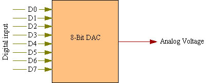
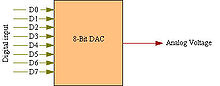 A simplified functional diagram of an 8-bit DAC
Audio
Most modern audio signals are stored in digital form (for example MP3s and CDs) and in order to be heard through speakers they must be converted into an analog signal. DACs are therefore found in CD players, digital music players, and PC sound cards.
Specialist standalone DACs can also be found in high-end hi-fi systems. These normally take the digital output of a compatible CD player or dedicated transport (which is basically a CD player with no internal DAC) and convert the signal into an analog line-level output that can then be fed into an amplifier to drive speakers.
Similar digital-to-analog converters can be found in digital speakers such as USB speakers, and in sound cards.
In VoIP (Voice over IP) applications, the source must first be digitized for transmission, so it undergoes conversion via an Analog-to-Digital Converter, and is then reconstructed into analog using a DAC on the receiving party's end.
 Top-loading CD player and external digital-to-analog converter.
Video
Video sampling tends to work on a completely different scale altogether thanks to the highly nonlinear response both of cathode ray tubes (for which the vast majority of digital video foundation work was targeted) and the human eye, using a "gamma curve" to provide an appearance of evenly distributed brightness steps across the display's full dynamic range - hence the need to use RAMDACs in computer video applications with deep enough colour resolution to make engineering a hardcoded value into the DAC for each output level of each channel impractical (e.g. an Atari ST or Sega Genesis would require 24 such values; a 24-bit video card would need 768...). Given this inherent distortion, it is not unusual for a television or video projector to truthfully claim a linear contrast ratio (difference between darkest and brightest output levels) of 1000:1 or greater, equivalent to 10 bits of audio precision even though it may only accept signals with 8-bit precision and use an LCD panel that only represents 6 or 7 bits per channel.
Video signals from a digital source, such as a computer, must be converted to analog form if they are to be displayed on an analog monitor. As of 2007, analog inputs were more commonly used than digital, but this changed as flat panel displays with DVI and/or HDMI connections became more widespread.[citation needed] A video DAC is, however, incorporated in any digital video player with analog outputs. The DAC is usually integrated with some memory (RAM), which contains conversion tables for gamma correction, contrast and brightness, to make a device called a RAMDAC.
A device that is distantly related to the DAC is the digitally controlled potentiometer, used to control an analog signal digitally.
Mechanical
An unusual application of digital-to-analog conversion was the whiffletree electromechanical digital-to-analog converter linkage in the IBM Selectric typewriter.[citation needed]
DAC types
The most common types of electronic DACs are:
- The pulse-width modulator, the simplest DAC type. A stable current or voltage is switched into a low-pass analog filter with a duration determined by the digital input code. This technique is often used for electric motor speed control, but has many other applications as well.
- Oversampling DACs or interpolating DACs such as the delta-sigma DAC, use a pulse density conversion technique. The oversampling technique allows for the use of a lower resolution DAC internally. A simple 1-bit DAC is often chosen because the oversampled result is inherently linear. The DAC is driven with a pulse-density modulated signal, created with the use of a low-pass filter, step nonlinearity (the actual 1-bit DAC), and negative feedback loop, in a technique called delta-sigma modulation. This results in an effective high-pass filter acting on the quantization (signal processing) noise, thus steering this noise out of the low frequencies of interest into the megahertz frequencies of little interest, which is called noise shaping. The quantization noise at these high frequencies is removed or greatly attenuated by use of an analog low-pass filter at the output (sometimes a simple RC low-pass circuit is sufficient). Most very high resolution DACs (greater than 16 bits) are of this type due to its high linearity and low cost. Higher oversampling rates can relax the specifications of the output low-pass filter and enable further suppression of quantization noise. Speeds of greater than 100 thousand samples per second (for example, 192 kHz) and resolutions of 24 bits are attainable with delta-sigma DACs. A short comparison with pulse-width modulation shows that a 1-bit DAC with a simple first-order integrator would have to run at 3 THz (which is physically unrealizable) to achieve 24 meaningful bits of resolution, requiring a higher-order low-pass filter in the noise-shaping loop. A single integrator is a low-pass filter with a frequency response inversely proportional to frequency and using one such integrator in the noise-shaping loop is a first order delta-sigma modulator. Multiple higher order topologies (such as MASH) are used to achieve higher degrees of noise-shaping with a stable topology.
- The binary-weighted DAC, which contains one resistor or current source for each bit of the DAC connected to a summing point. These precise voltages or currents sum to the correct output value. This is one of the fastest conversion methods but suffers from poor accuracy because of the high precision required for each individual voltage or current. Such high-precision resistors and current sources are expensive, so this type of converter is usually limited to 8-bit resolution or less.
- The R-2R ladder DAC which is a binary-weighted DAC that uses a repeating cascaded structure of resistor values R and 2R. This improves the precision due to the relative ease of producing equal valued-matched resistors (or current sources). However, wide converters perform slowly due to increasingly large RC-constants for each added R-2R link.
- The thermometer-coded DAC, which contains an equal resistor or current-source segment for each possible value of DAC output. An 8-bit thermometer DAC would have 255 segments, and a 16-bit thermometer DAC would have 65,535 segments. This is perhaps the fastest and highest precision DAC architecture but at the expense of high cost. Conversion speeds of >1 billion samples per second have been reached with this type of DAC.
- Hybrid DACs, which use a combination of the above techniques in a single converter. Most DAC integrated circuits are of this type due to the difficulty of getting low cost, high speed and high precision in one device.
- The segmented DAC, which combines the thermometer-coded principle for the most significant bits and the binary-weighted principle for the least significant bits. In this way, a compromise is obtained between precision (by the use of the thermometer-coded principle) and number of resistors or current sources (by the use of the binary-weighted principle). The full binary-weighted design means 0% segmentation, the full thermometer-coded design means 100% segmentation.
DAC performance
DACs are very important to system performance. The most important characteristics of these devices are:
- Resolution: This is the number of possible output levels the DAC is designed to reproduce. This is usually stated as the number of bits it uses, which is the base two logarithm of the number of levels. For instance a 1 bit DAC is designed to reproduce 2 (21) levels while an 8 bit DAC is designed for 256 (28) levels. Resolution is related to the Effective number of bitswhich is a measurement of the actual resolution attained by the DAC. Resolution determines color depth in video applications and audio bit depth in audio applications.
- Maximum sampling rate: This is a measurement of the maximum speed at which the DACs circuitry can operate and still produce the correct output. As stated in the Nyquist–Shannon sampling theorem defines a relationship between the sampling frequency and bandwidth of the sampled signal.
- Monotonicity: This refers to the ability of a DAC's analog output to move only in the direction that the digital input moves (i.e., if the input increases, the output doesn't dip before asserting the correct output.) This characteristic is very important for DACs used as a low frequency signal source or as a digitally programmable trim element.
- THD+N: This is a measurement of the distortion and noise introduced to the signal by the DAC. It is expressed as a percentage of the total power of unwanted harmonic distortion and noise that accompany the desired signal. This is a very important DAC characteristic for dynamic and small signal DAC applications.
- Dynamic range: This is a measurement of the difference between the largest and smallest signals the DAC can reproduce expressed in decibels. This is usually related to resolution and noise floor.
Other measurements, such as phase distortion and jitter, can also be very important for some applications, some of which (e.g. wireless data transmission, composite video) may even rely on accurate production of phase-adjusted signals.
Linear PCM audio sampling usually works on the basis of each bit of resolution being equivalent to 6 decibels of amplitude (a 2x increase in volume or precision).
Non-linear PCM encodings (A-law / mu-law, ADPCM, NICAM) attempt to improve their effective dynamic ranges by a variety of methods - logarithmic step sizes between the output signal strengths represented by each data bit (trading greater quantisation distortion of loud signals for better performance of quiet signals)
DAC figures of merit
- Static performance:
- Differential nonlinearity (DNL) shows how much two adjacent code analog values deviate from the ideal 1 LSB step.[1]
- Integral nonlinearity (INL) shows how much the DAC transfer characteristic deviates from an ideal one. That is, the ideal characteristic is usually a straight line; INL shows how much the actual voltage at a given code value differs from that line, in LSBs (1 LSB steps).
- Gain
- Offset
- Noise is ultimately limited by the thermal noise generated by passive components such as resistors. For audio applications and in room temperatures, such noise is usually a little less than 1 μV (microvolt) of white noise. This limits performance to less than 20~21 bits even in 24-bit DACs.
- Frequency domain performance
- Spurious-free dynamic range (SFDR) indicates in dB the ratio between the powers of the converted main signal and the greatest undesired spur.
- Signal-to-noise and distortion ratio (SNDR) indicates in dB the ratio between the powers of the converted main signal and the sum of the noise and the generated harmonic spurs
- i-th harmonic distortion (HDi) indicates the power of the i-th harmonic of the converted main signal
- Total harmonic distortion (THD) is the sum of the powers of all HDi
- If the maximum DNL error is less than 1 LSB, then the D/A converter is guaranteed to be monotonic. However, many monotonic converters may have a maximum DNL greater than 1 LSB.
- Time domain performance:
- Glitch energy
- Response uncertainty
- Time nonlinearity (TNL)
See also
References
Further reading
- Kester, Walt, The Data Conversion Handbook, ISBN 0-7506-7841-0, http://www.analog.com/library/analogDialogue/archives/39-06/data_conversion_handbook.html
- S. Norsworthy, Richard Schreier, Gabor C. Temes, Delta-Sigma Data Converters. ISBN 0-7803-1045-4.
- Mingliang Liu, Demystifying Switched-Capacitor Circuits. ISBN 0-7506-7907-7.
- Behzad Razavi, Principles of Data Conversion System Design. ISBN 0-7803-1093-4.
- Phillip E. Allen, Douglas R. Holberg, CMOS Analog Circuit Design. ISBN 0-19-511644-5.
- Robert F. Coughlin, Frederick F. Driscoll, Operational Amplifiers and Linear Integrated Circuits. ISBN 0-13-014991-8.
External links
Categories:- Digital signal processing
- Electronic circuits


Wikimedia Foundation. 2010.