- MISTRAM
-
 MISTRAM Missile Trajectory Measurement System.
MISTRAM (MISsile TRAjectory Measurement) was a high-resolution tracking system used by the United States Air Force (and later NASA) to provide highly detailed trajectory analysis of rocket launches.
A "classic" ranging system used since the 1960s uses radar to time a radio signal's travel to a target (in this case, the rocket) and back. This technique is accurate to approximately 1%. The accuracy of this technique is limited by the need to create a sharp "pulse" of radio so that the start of the signal can be accurately defined. There are both practical and theoretical limits to the sharpness of the pulse. In addition, the timing of the signals often introduced inaccuracies of its own until the introduction of high precision clocks.
In MISTRAM, this was avoided by broadcasting a continuous signal. The basic system used a ground station located down range from the launch site (at Valkaria, Florida and Eleuthera Island, Bahamas) and a transponder on the vehicle. The tracking station transmitted an X-band carrier signal which the transponder responded to by re-broadcasting it on another (shifted) frequency. By slowly changing the frequency of the carrier broadcast from the station and comparing this with the phase of the signal being returned, ground control could measure the distance to the vehicle very accurately. Even with the analog circuitry used, MISTRAM was accurate to less than 1 km at the distance of the moon.
 US Air Force Eastern Test Range (Historical Map).
To meet more stringent ballistic missile test requirements, several systems were designed, procured and added to the US Air Force Eastern Range's instrumentation in the 1950s and 1960s. The AZUSA continuous wave tracking system was added to the Cape in the mid-1950s and Grand Bahama in the early 1960s. The AN/FPS-16 radar system was introduced at the Cape, Grand Bahama, San Salvador, Ascension and East Grand Bahama Island between 1958 and 1961. In the early 1960s, the MISTRAM (Missile Trajectory Measurement) system was installed at Valkaria, Florida and Eleuthera island in the Bahamas to support Minuteman missile flights.
Contents
Principles of Operation
 Five receiving stations on 10,000 ft and 100,000 ft baselines receive signals from missile, compute the velocity, position and trajectory.
MISTRAM is a sophisticated interferometer system consisting of a group of five receiving stations arranged in an L shape. Baselines are 10,000 ft (3,000 m). and 100,000 ft (30,000 m). The central stations contains a simple tracking antenna. The distance from the central station to the furthest remote station is approximately 100,000 ft (30,000 m). Antennas at the central station and the four remote stations follow the flight of a missile and receive signals from its radio beacon.
In the MISTRAM system, the ground station transmits a carrier to the spacecraft and the spacecraft returns this carrier on another frequency. The ground station sweeps the uplink carrier and the phase shift of the downlink carrier is measured (counted) while it is being swept. The round trip delay time can be shown to be T=(delta-phi)/(delta-f) ; where delta-f is the frequency shift (~4000 Hz for example) and delta-phi the measured phase shift in radians. Suppose T=2 sec (~lunar distance) then delta-phi=8000 radians, i.e. (8000*180)/Pi. Assume also that the phase can be measured with an accuracy of 1 deg, i.e. means that the range can be determined with a precision of (600000*1*Pi)/(2*8000*180)=0.33 km. An additional carrier quite near the one described above that remained fixed in frequency and used as a phase reference. That carrier and the two frequencies (that the sweep changed between) were generated as multiples of the same basic oscillator frequency. In this way, all signals would have a fixed phase relationship, as was done in MISTRAM. A similar technique was used in the Soviet Luna 20 spacecraft at 183.54 MHz to survey the moon's surface.[1]
MISTRAM was a multistatic long baseline radar interferometer developed for precision measurements of missile trajectories at the US Air Force Eastern Test Range. Multistatic radar systems have a higher complexity with multiple transmitter and receiver subsystems employed in a coordinated manner at more than two sites. All of the geographically dispersed units contribute to the collective target acquisition, detection, position finding and resolution, with simultaneous reception at the receiver sites. In a simpler sense, multistatic radars are systems which have two or more receiving sites with a common spatial coverage area, and data from these coverage areas are combined and processed at a central location. These systems are considered to be multiple bistatic pairs. Multistatic radar systems have various uses, including prevention of jamming and anti-radar munitions.
Although this method of measurement is not new, either in theory or in practice, the unique manner in which the techniques were implemented in the MISTRAM system permit measurement of vehicle flight parameters with a degree of precision and accuracy not previously obtainable in other long baseline trajectory measurement systems. To a large extent, this was accomplished by a unique method of transferring intact the phase information in the signals from outlying stations to the central station. A two-way transmission path on each baseline was used to cancel out uncertainties due to variance in ground geometry and temperature.[2]
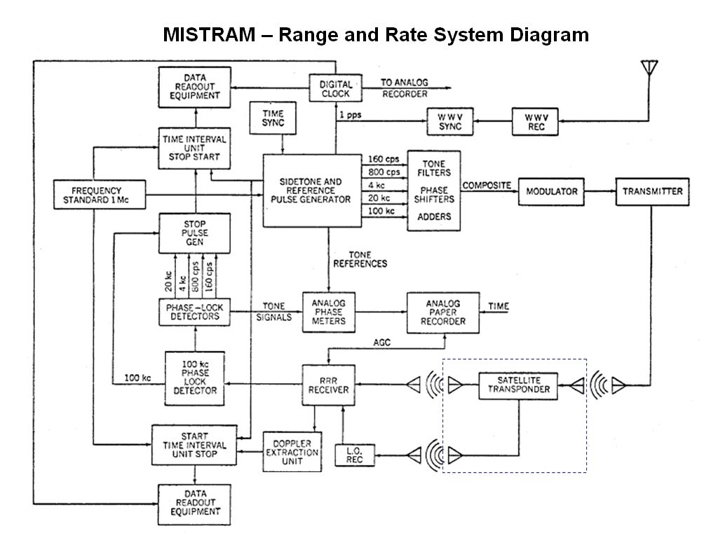
 MISTRAM block diagram shows ground-based components and airborne transponder.
The transmitter at the master or central station generates two CW X-band frequencies, nominally 8148 MHz and 7884 to 7892 MHz. The higher frequency (the range signal) is very stable, whereas the lower frequency (the calibrated signal) is swept periodically over the indicated range. The airborne transponder receives the signals, amplifies & frequency shifts them by 68 MHz, and retransmits back to earth. The Doppler shift is used to determine velocity.[3]
The Florida MISTRAM system had 100,000 ft (30,000 m) baselines (~18.9 mi.) with design performance as follows:
Range of Operation 0 to 50,000 ft/s (0 to 15,000 m/s) 0 to 750 ft/s2 (0 to 230 m/s2) 360 deg 5 to 85 deg 20 to 1,000 mi (1,600 km) Measurement Uncertainties (RMS) 0.4 ft (0.12 m) 0.3 ft (91 mm) 0.02 ft/s (Template:Convert/mm/s)[n 1][2] 0.002 ft/s (Template:Convert/mm/s)[n 1][2] MISTRAM Transponder
 MISTRAM "A" Model Transponder
The Transponder receives the two phase-coherent X-band cw signals transmitted from the ground equipment. A klystron with a 68 MHz coherent frequency offset is phase locked to each of the received signals. These klystrons provide the phase coherent return transmission. There are two separate phase locked loops, continuous and calibrate.
- MISTRAM "A" Model Transponder Specifications
-
- Operating Frequencies (Nominal)
- Continuous - 8148 MHz received
- 8216 MHz transmitted
- Calibrate - 7884 to 8992 (swept) received
- 7952 to 7960 (swept) transmitted
- Input power - 5.25 amps maximum from 25.2 to 32.2 V DC
- Output power - 500 mW min/channel
- Warmup time - 1 minute maximum at 0 degrees Celsius or above
- Acquisition Time - 0.1 second maximum
- Phase coherence - 256 MHz - within 45 degrees (0.25 foot range error max.)
- 8 MHz - within 2 degrees (0.36 ft (110 mm) range error max.)
- Dynamic range = -39 to -105 dBm
- Physical characteristics
- Size: 8.9×12.4×5.4 in (230×310×140 mm) (including mounting projections)
- Waveguide ports: Two reduced height X-band (1 Xmit; 1 Rcv)
- Life: 3 years. Operating 500 hours.
M-236 Computer
The General Electric M236 computer was developed to support MISTRAM and other large military radar projects in the 1960s. (According to Dr. Neelands, certain military people involved in the project were adamant about not relying on "computers", therefore this "information processor" was developed.) This high speed 36-bit minicomputer was developed by the GE Heavy Military Electronics Department (HMED) in Syracuse, New York, eventually leading to the GE-600 series of mainframe computers. The M236 was designed for real-time processing in a radar-based missile flight measurement system and lacked some general purpose features, such as overlapped instruction processing, the floating point operations needed for Fortran, and operating system support features, such as base and bounds registers.[4] The M-236 computer was developed for the US Air Force Cape Canaveral Missile Range, and installed it at Eleuthera (Bahamas). The 36-bit computer word length was needed for radar tracking computations and for the required exchange of data with an IBM 7094 located at the Cape. The chief architect of the M-236 was John Couleur who will become later a technical leader of the GE large computer systems.
The debate in favor or against subsequent development of an M236-derived general purpose computer took more than one year and concluded finally with the victory of the M2360 project proponents in February 1963. The GE upper management was impressed by the opportunity to save the rental fees from IBM leased equipment used internally by GE (the cost of development of the new project was estimated to be offset by only one year of rentals). The other GE departments were not very impressed and were reluctant to jettison their IBM machines.[5]
The GE-600 series was developed by a team led by John Couleur based on work done for the MISTRAM project in 1959. MISTRAM was a missile tracking system that was used on a number of projects (including Project Apollo) and the Air Force required a data-collection computer to be installed in a tracking station downrange from Cape Canaveral. The data would eventually be shared with the 36-bit IBM 7094 machine at the Cape, so the computer would likely have to be 36-bits as well (why they didn't use an IBM 7094 is something of a mystery). GE built a machine called the M236 for the task, and as a result of the 36-bit needs, it ended up acting a lot like the 7094.[6]
The GE Heavy Military Electronics Department in Syracuse designed and built a tracking system for the ATLAS missile system named MISTRAM that was in fact an advanced computer system. This was quite in accordance with Cordiner’s directions since it would not develop a line of machines that be placed on the open market in competition with IBM. (Ralph J. Cordiner was Chairman & CEO of General Electric from 1958 to 1963.) This project also had the advantage that the up front development expenditures were to be paid by the U.S. government rather than GE, an arrangement much more satisfactory to GE's 570 “bean counters.” These circumstances brought about the possibility of duplicating the MISTRAM opportunity for the computer department. Much later, the result was an order for 32 computer department machines. However, the MISTRAM computer was the first in a line of developments by John Couleur that led to what may be regarded as the most successful and long-lasting machine - the GE 600 line.[7]
Applications
MISTRAM was used in the development and testing of intertial guidance system for the Minuteman ballistic missile, and subsequently was used for testing the Gemini spacecraft and the Saturn V launch system. With the decommissioning of the MISTRAM X-band interferometer at the Air Force Eastern Test Range in 1971, the flight-test community did not have a conventional ground-based range-instrumentation system better than, or comparable to, the inertial guidance systems whose performance was being assessed.[8] This was true in the intervening years preceding GPS development and deployment.
Minuteman Inertial Guidance System Testing
The first Minuteman missiles (MM I) were launched in the early 1960s from the Air Force Eastern Test Range (AFETR) and were tracked with the AZUSA CW tracking system. The comparatively low quality of the AZUSA tracking data, combined with the rudimentary stage of evaluation techniques, allowed only estimation of the total error; no isolation of individual inertial measurement unit (IMU) error sources was possible.[9]
Subsequent development of improved tracking systems, UDOP and MISTRAM, at AFETR yielded much higher quality velocity tracking profiles. During the Minuteman II flight test program, significant improvements were made in the post-flight evaluation of the IMU accuracy. The most important of these improvement was the introduction of maximum likelihood error estimation using the Kalman algorithm to filter the velocity error profile. Continued improvement of the UDOP and MISTRAM tracking systems and refinement of the evaluation techniques during the Minuteman III flight test program made it possible to gain considerable insight into NS-20A1 IMU error sources.[9]
Accuracy evaluation
One of the major problems in trajectory and orbital estimation is to obtain a realistic estimate of the accuracy of the trajectory and other important parameters. In the orbital case, some of the parameters which may not be solved for are geopotential constants, survey, etc. These factors will affect the total uncertainty in the orbit and, of course, ephemeris predictions. A statistical technique was developed that performs a variance-covariance propagation to obtain accuracy estimates based on random and unmodeled errors. An example of the unmodeled error propagation in the MISTRAM system was given for the Geos B satellite.[10]
Key Personnel
Dr. Lewis J. Neelands has been called an engineers' engineer by the people who worked with him when he was with the General Electric Corporation Electronics Laboratory and Heavy Military Electronics Department (HMED) in the 1950s and early 60's. His contributions to missile guidance and telemetry made him a key figure in the Altas Guidance and MISTRAM programs, two of HMED's most challenging and successful efforts.[11]
In retrospect, Neelands said he did not get his greatest satisfaction from his work on the Atlas guidance (about which he said,"it was successful because of a bunch of other people who put it together and made it work"). It is MISTRAM, missile tracking and measuring system, that he remembers with greater pride. "Nothing could match it at the time for the complexity and precision it required," he recalls of the real-time measuring system for precisely tracking a missile's flight. One of his colleagues remembers, "In 1960 he solved the elusive problem of trajectory measurement -- of bringing together at one place for processing, the signals received from widely spaced receiving stations while overcoming inaccuracies due to the propagation anomalies in the medium connecting the stations. A related problem that Lew solved was how to do this using frequencies sufficiently high to develop the required angular measurement accuracy without measurement ambiuities and without requiring a large number of receiving stations to resolve these anbiguities." He conceived a system of unprecedented accuracy.[10] The technical work on the Hermes A-3 rocket guidance was headed by Dr. Lewis J. Neelands and resulted in a successful system with the know-how later transferred to another ICBM guidance system known as the 8014 project and also to the highly accurate Mistram instrumentation equipment, all were based on use of a microwave interferometer.[11] Dr. Neelands passed away at his home in Gainesville Florida on July 17, 2007 at the age of 91.
References
- ^ Sven Grahn. "Reception of signals on 183.54 MHz from the Luna 20 return spacecraft in Stockholm". Sollentuna, Sweden. http://www.svengrahn.pp.se/trackind/luna20/LUNA20.htm.
- ^ a b c R.A. Heartz and T.H. Jones (July 1962). "Mistram and rendezvous". Astronautics 7: 47–50.
- ^ Jerome Hoffman (Jan-Feb 1965). Journal of Spacecraft 2 (1): 55–61.
- ^ Jane King and William A. Shelly (1997). "A family history of Honeywell's large-scale computer systems". IEEE Annals of the History of Computing 19 (4): 42–46.
- ^ Jean Bellec (FEB). "From GECOS to GCOS8 - A History of Large Systems in GE, Honeywell, NEC and Bull". http://www.feb-patrimoine.com/english/gecos_to_gcos8_part_1.htm.
- ^ John Couleur (Winter, 1995). "The Core of the Black Canyon Computer Corporation". IEEE Annals of the History of Computing 17 (4): 56–60.
- ^ J.A.N. Lee (Winter 1995). "The Rise and Fall of the General Electric Corporation Computer Department". IEEE Annals of the History of Computing 17 (4): 24–45.
- ^ Thomas P. Nosek (1982). "Space Shuttle as a Dynamic Test Tool for Missile Guidance Systems". J. Guidance 6 (6): 530 ff.
- ^ a b R. Fuessel, J. McGhee, R. Powers, and D. Sifter. "A method for determining the performance of a precision inertial guidance system". AIAA Guidance and Control Conference, August 6–8, 1979, Boulder, Colorado. AIAA Paper No. 1979-1891. pp. 637-644.
- ^ a b Norman Bush (May 1971). "Unmodeled Error Analysis on Trajectory and Orbital Estimation". Technometrics 13 (2): 303–314.
- ^ a b Kevin Neelands. "Dr. Lewis J. Neelands biography on 100th anniversary of General Electric Co". http://user.gru.net/nemesis/dadbio.htm.
- Chronology
MISTRAM was designed and developed by the Heavy Military Electronics Division, Defense Systems Department of the General Electric Company, Syracuse, New York, under the sponsorship of the U.S. Air Force Missile Test Center, Patrick Air Force Base, Florida (Contract AF08 (6060) 4891). Mistram I at Valkaria, FL was placed into operation in 1962 and Mistram II at Eleuthera, Bahamas in 1963. The original contract for $15.5M was announced on July 12, 1960.
- Dissertations
MISTRAM has been the topic of several dissertations for master of science degrees in engineering.
- Henry F Kerr. A case study : Development of the Mistram type B transponder. Thesis (M.S.)--Florida State University, 1966. 33 pp. OCLC: 44949051
- William R Threlkeld. An application of refraction measurements to improve MISTRAM tracking accuracy. Dissertation: Thesis (M.S.)--Florida State University. 1965. 97 pp. OCLC: 10939666
- Thomas Irvin Osborn. Mistram—a missile trajectory measurement system. Dissertation: Thesis (M.S.)--Syracuse University, 1964. 56 pp. OCLC: 79314654
Categories:


Wikimedia Foundation. 2010.