- Optical time-domain reflectometer
-
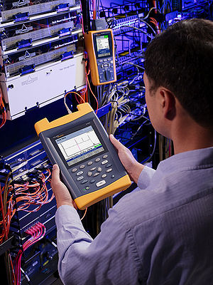 Fluke Networks OTDR in use
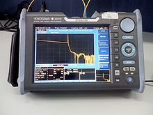 Yokogawa's OTDR
An optical time-domain reflectometer (OTDR) is an optoelectronic instrument used to characterize an optical fiber. An OTDR injects a series of optical pulses into the fiber under test. It also extracts, from the same end of the fiber, light that is scattered (Rayleigh backscatter) or reflected back from points along the fiber. (This is equivalent to the way that an electronic time-domain reflectometer measures reflections caused by changes in the impedance of the cable under test.) The strength of the return pulses is measured and integrated as a function of time, and is plotted as a function of fiber length.
Contents
Description
An OTDR may be used for estimating the fiber's length and overall attenuation, including splice and mated-connector losses. It may also be used to locate faults, such as breaks, and to measure optical return loss. To measure the attenuation of multiple fibers, it is advisable to test from each end and then average the results, however this considerable extra work is contrary to the common claim that testing can be performed from only one end of the fiber.
In addition to required specialized optics and electronics, OTDRs have significant computing ability and a graphical display, so they may provide significant test automation. However, proper instrument operation and interpretation of an OTDR trace still requires special technical training and experience.
OTDRs are commonly used to characterize the loss and length of fibers as they go from initial manufacture, through to cabling, warehousing while wound on a drum, installation and then splicing. The last application of installation testing is more challenging, since this can be over extremely long distances, or multiple splices spaced at short distances, or fibers with different optical characteristics joined together. OTDR test results are often carefully stored in case of later fiber failure or warranty claims. Fiber failures can be very expensive, both in terms of the direct cost of repair, and consequential loss of service.
OTDRs are also commonly used for fault finding on installed systems. In this case, reference to the installation OTDR trace is very useful, to determine where changes have occurred. Use of an OTDR for fault finding may require an experienced operator who is able to correctly judge the appropriate instrument settings to locate a problem accurately. This is particularly so in cases involving long distance, closely spaced splices or connectors, or PONs.
OTDRs are available with a variety of fiber types and wavelengths, to match common applications. In general, OTDR testing at longer wavelengths, such as 1550 nm or 1625 nm, can be used to identify fiber attenuation caused by fiber problems, as opposed to the more common splice or connector losses.
The optical dynamic range of an OTDR is limited by a combination of optical pulse output power, optical pulse width, input sensitivity, and signal integration time. Higher optical pulse output power, and better input sensitivity, combine directly to improve measuring range, and are usually fixed features of a particular instrument. However optical pulse width and signal integration time are user adjustable, and require trade-offs which make them application specific.
A longer laser pulse improves dynamic range and attenuation measurement resolution at the expense of distance resolution. For example, using a long pulse length, it may possible to measure attenuation over a distance of more than 100 km, however in this case an optical event may appear to be over 1 km long. This scenario is useful for overall characterisation of a link, but would be of much less use when trying to locate faults. A short pulse length will improve distance resolution of optical events, but will also reduce measuring range and attenuation measurement resolution. The "apparent measurement length" of an optical event is referred to as the "dead zone". The theoretical interaction of pulse width and dead zone can be summarised as follows:
Pulse length Event Dead zone 1 nsec 0.15 m ( theoretically ) 10 nsec 1.5 m ( theoretically ) 100 nsec 15 m 1 µsec 150 m 10 µsec 1.5 km 100 µsec 15 km 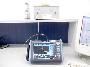
The OTDR "dead zone" is a topic of much interest to users. Dead zone is classified in two ways. Firstly, an "Event Dead Zone" is related to a reflective discrete optical event. In this situation, the measured dead zone will depend on a combination of the pulse length (see table), and the size of the reflection. Secondly, an "Attenuation Dead Zone" is related to a non-reflective event. In this situation, the measured dead zone will depend on a combination of the pulse length (see table).
A long signal integration time effectively increases OTDR sensitivity by averaging the receiver output. The sensitivity increases with the square root of the integration time. So if the integration time is increased by 16 times, the sensitivity increases by a factor of 4. This imposes a sensitivity practical limit, with integration times of seconds to a few minutes.
The dynamic range of an OTDR is usually specified as the attenuation level where the measured signal gets lost in the detection noise level, for a particular combination of pulse length and signal integration time. This number is easy to deduce by inspection of the output trace, and is useful for comparison, but is not very useful in practice, since at this point the measured values are random. So the practical measuring range is smaller, depending on required attenuation measurement resolution.
When an OTDR is used to measure the attenuation of multiple joined fiber lengths, the output trace can incorrectly show a joint as having gain, instead of loss. The reason for this is that adjacent fibers may have different backscatter coefficients, so the second fiber reflects more light than the first fiber, with the same amount of light travelling through it. If the OTDR is placed at the other end of this same fiber pair, it will measure an abnormally high loss at that joint. However if the two signals are then combined, the correct loss will be obtained. For this reason, it is common OTDR practice to measure and combine the loss from both ends of a link, so that the loss of cable joints, and end to end loss, can be more accurately measured.
The theoretical distance measuring accuracy of an OTDR is extremely good, since it is based on software and a crystal clock with an inherent accuracy of better than 0.01%. This aspect does not need subsequent calibration since practical cable length measuring accuracy is typically limited to about 1% due to: The cable length is not the same as the fiber length, the speed of light in the fiber is known with limited accuracy (the refractive index is only specified to 3 significant figures such as e.g. 1.45 etc.), and cable length markers have limited accuracy (0.5% – 1%).
An OTDR excels at identifying the existence of unacceptable point loss or return loss in cables. Its ability to accurately measure absolute end-to-end cable loss or return loss can be quite poor, so cable acceptance usually includes an end-to-end test with a light source and power meter, and optical return loss meter. Its ability to exactly locate a hidden cable fault is also limited, so for fault-finding it may be augmented with other localised tools such as a red laser fault locator, clip-on identifier, or "Cold Clamp" optical cable marker.
Reliability and quality of OTDR equipment
The reliability and quality of an OTDR should be determined on the basis of its accuracy, measurement range, ability to resolve and measure closely spaced events, the speed at which it makes measurements, and its ability to perform satisfactorily under various environmental extremes and after various types of physical abuses. In addition to its cost, the instrument should also be rated on the features provided, its size, its weight, and how simple it is to operate.
Accuracy is defined as the correctness of the measurement (i.e., the difference between the measured value and the true value of the event being measured).
The measurement range of the OTDR is defined as the maximum attenuation that can be placed between the instrument and the event being measured, for which the instrument will still be able to measure the event within acceptable accuracy limits.
Instrument resolution is a measure of how close two events can be spaced and still be recognized as two separate events. The duration of the measurement pulse and the data sampling interval create a resolution limitation for OTDRs: the shorter the pulse duration and the shorter the data sampling interval, the better the instrument resolution, but the shorter the measurement range. Resolution is also often limited when powerful reflections return to the OTDR and temporarily overload the detector circuitry. When this occurs, some time is required before the instrument can resolve a second fiber event. Some OTDR manufacturers use a “masking” procedure to improve resolution. The procedure shields or “masks” the detector from high-power fiber reflections, preventing detector overload and eliminating the need for detector recovery.
Industry requirements for the reliability and quality of OTDRs are in GR-196, Generic Requirements for Optical Time Domain Reflectometer (OTDR) Type Equipment.
Types of OTDR-like test equipment
The common types of OTDR-like test equipment are:
- Full-feature OTDR
- Hand-held OTDR
- Fiber Break Locator
- RTU in RFTSs
The equipment is summarized below, and detailed in GR-196, Generic Requirements for Optical Time Domain Reflectometer (OTDR) Type Equipment.
- Full-feature OTDR
- Full-feature OTDRs are traditional, optical time domain reflectometers. They are feature-rich and usually larger, heavier, and less portable than either the hand-held OTDR or the fiber break locator. Despite being characterized as large, their size and weight is only a fraction of that of early generation OTDRs. Often a full-feature OTDR has a main frame that can be fitted with multi-functioned plug-in units to perform many different fiber measurement tasks. Larger, color displays are common. The full-feature OTDR often has a greater measurement range than the other types of OTDR-like equipment. Often it is used in laboratories and in the field for difficult fiber measurements. Most full-feature OTDRs are powered from an AC source and or battery source.
- Hand-held OTDR and Fiber break locator
- Hand-held (formerly mini) OTDRs and fiber break locators are designed to troubleshoot fiber networks in a field-type environment often using battery power. The two types of instruments cover the spectrum of approaches to fiber optic plant taken by the communications providers. Hand-held, inexpensive (compared to full-feature) OTDRs are intended to be easy-to-use, light-weight, sophisticated OTDRs to collect field data and perform rudimentary data analysis upon. They may be less feature rich than full-feature OTDRs. Often they can be used in conjunction with PC-based software to perform easy data collection with the hand-held OTDR and sophisticated data analysis with the PC-based software. The hand-held OTDRs are commonly used to measure fiber links and locate fiber breaks, points of high loss, points of high reflectance, link end-to-end loss, and Optical Return Loss (ORL) for the link.
- Fiber break locators are intended to be low-cost instruments specifically designed to locate the position of a catastrophic fiber event, e.g., fiber break, point of high reflectance, or high loss. The fiber break locator is an opto-electronic tape measure that is designed to measure only distance to catastrophic fiber events.
- In general, hand-held OTDRs and fiber break locators are lighter and smaller, simpler to operate, and more likely to operate using battery power than full-feature OTDRs. The intent is for hand-held OTDRs and fiber break locators to be inexpensive enough for optical technicians to be equipped with one as part of their standard tool kit.
- Remote Test Unit (RTU)
- The RTU is the testing module of the RFTS described in GR-1295, Generic Requirements for Remote Fiber Testing Systems (RFTSS). An RFTS enables fiber physical plant to be automatically tested from a central location. A central computer is used to control the operation of OTDR-like test components located at key points in the fiber network. These test components will scan the fiber to locate problems. If a problem is found, its location is noted and the appropriate Operations Systems (OSs) are notified to begin the repair process. The RFTS can also provide direct access to a corporate database that contains a historical repository for the OTDR fiber traces and any other fiber records for the physical fiber plant.
- Since OTDRs and OTDR-like equipment have many uses in the communications industry, their possible operating environment is varied, ranging from indoors to outdoors. Most often, however, these test sets are operated in controlled environments, accessing the fibers at their termination points on fiber distributing frames. Indoor environments include controlled environments such as in central offices (COs), equipment huts, or Controlled Environment Vaults (CEVs). Use in outside environments is rarer, but may include use in a manhole, aerial platform, open trench, or a splicing van.
See also
- Optical return loss
External links
 This article incorporates public domain material from the General Services Administration document "Federal Standard 1037C".Categories:
- Fiber-optic communications
- Telecommunications equipment
- Fiber optics


Wikimedia Foundation. 2010.