- Buffer amplifier
-
A buffer amplifier (sometimes simply called a buffer) is one that provides electrical impedance transformation from one circuit to another. Two main types of buffer exist: the voltage buffer and the current buffer.
 Figure 1: Top: Ideal voltage buffer Bottom: Ideal current buffer
Contents
Voltage buffer
A voltage buffer amplifier is used to transfer a voltage from a first circuit, having a high output impedance level, to a second circuit with a low input impedance level. The interposed buffer amplifier prevents the second circuit from loading the first circuit unacceptably and interfering with its desired operation. In the ideal voltage buffer in the diagram, the input resistance is infinite, the output resistance zero (impedance of an ideal voltage source is zero). Other properties of the ideal buffer are: perfect linearity, regardless of signal amplitudes; and instant output response, regardless of the speed of the input signal.
If the voltage is transferred unchanged (the voltage gain Av is 1), the amplifier is a unity gain buffer; also known as a voltage follower because the output voltage follows or tracks the input voltage. Although the voltage gain of a voltage buffer amplifier may be (approximately) unity, it usually provides considerable current gain and thus power gain. However, it is commonplace to say that it has a gain of 1 (or the equivalent 0 dB), referring to the voltage gain.
As an example, consider a Thévenin source (voltage VA, series resistance RA) driving a resistor load RL. Because of voltage division (also referred to as "loading") the voltage across the load is only VA RL / ( RL + RA ). However, if the Thévenin source drives a unity gain buffer such as that in Figure 1 (top, with unity gain), the voltage input to the amplifier is VA, with no voltage division because the amplifier input resistance is infinite. At the output the dependent voltage source delivers voltage Av VA = VA to the load, again without voltage division because the output resistance of the buffer is zero. A Thévenin equivalent circuit of the combined original Thévenin source and the buffer is an ideal voltage source VA with zero Thévenin resistance.
Current buffer
Typically a current buffer amplifier is used to transfer a current from a first circuit, having a low output impedance level, to a second circuit with a high input impedance level. The interposed buffer amplifier prevents the second circuit from loading the first circuit unacceptably and interfering with its desired operation. In the ideal current buffer in the diagram, the input impedance is infinite and the output impedance is zero (impedance of an ideal current source is infinite). Again, other properties of the ideal buffer are: perfect linearity, regardless of signal amplitudes; and instant output response, regardless of the speed of the input signal.
For a current buffer, if the current is transferred unchanged (the current gain βi is 1), the amplifier is again a unity gain buffer; this time known as a current follower because the output current follows or tracks the input current.
As an example, consider a Norton source (current IA, parallel resistance RA) driving a resistor load RL. Because of current division (also referred to as "loading") the current delivered to the load is only IA RA / ( RL + RA ). However, if the Norton source drives a unity gain buffer such as that in Figure 1 (bottom, with unity gain), the current input to the amplifier is IA, with no current division because the amplifier input resistance is zero. At the output the dependent current source delivers current βi IA = IA to the load, again without current division because the output resistance of the buffer is infinite. A Norton equivalent circuit of the combined original Norton source and the buffer is an ideal current source IA with infinite Norton resistance.
Voltage buffer examples
Op-amp implementation
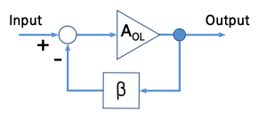 Figure 2: A negative feedback amplifier
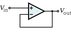 Figure 3. An op-amp–based unity gain buffer amplifier
A unity gain buffer amplifier may be constructed by applying a full series negative feedback (Fig. 2) to an op-amp simply by connecting its output to its inverting input, and connecting the signal source to the non-inverting input (Fig. 3). In this configuration, the entire output voltage (β = 1 in Fig. 2) is placed contrary and in series with the input voltage. Thus the two voltages are subtracted according to Kirchoff's voltage law (KVL) and their difference is applied to the op-amp differential input. This connection forces the op-amp to adjust its output voltage simply equal to the input voltage (Vout follows Vin so the circuit is named op-amp voltage follower).
The importance of this circuit does not come from any change in voltage, but from the input and output impedances of the op-amp. The input impedance of the op-amp is very high (1 MΩ to 10 TΩ), meaning that the input of the op-amp does not load down the source and draws only minimal current from it. Because the output impedance of the op-amp is very low, it drives the load as if it were a perfect voltage source. Both the connections to and from the buffer are therefore bridging connections, which reduce power consumption in the source, distortion from overloading, crosstalk and other electromagnetic interference.
Single-transistor circuits
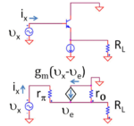 Figure 4: Top: BJT voltage follower Bottom: Small-signal, low-frequency equivalent circuit using hybrid-pi model
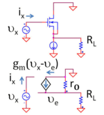 Figure 5: Top: MOSFET voltage follower Bottom: Small-signal, low-frequency equivalent circuit using hybrid-pi model
Other unity gain buffer amplifiers include the bipolar junction transistor in common-collector configuration (called an emitter follower because the emitter voltage follows the base voltage, or a voltage follower because the output voltage follows the input voltage); the field effect transistor in common-drain configuration (called a source follower because the source voltage follows the gate voltage or, again, a voltage follower because the output voltage follows the input voltage); or similar configurations using vacuum tubes (cathode follower), or other active devices. All such amplifiers actually have a gain of slightly less than unity, but the difference is usually small and unimportant.
Impedance transformation using the bipolar voltage follower
Using the small-signal circuit in Figure 4, the impedance seen looking into the circuit is
-
 .
.
(The analysis uses the relation gmrπ = (IC /VT) (VT /IB) = β, which follows from the evaluation of these parameters in terms of the bias currents.) Assuming the usual case where rO >> RL, the impedance is looking into the buffer is larger than the load RL without the buffer by a factor of (β +1), which is substantial because β is large. The impedance is increased even more by the added rπ, but often rπ << (β +1) RL, so the addition does not make much difference
Impedance transformation using the MOSFET voltage follower
Using the small-signal circuit in Figure 5, the impedance seen looking into the circuit is no longer RL but instead is infinite (at low frequencies) because the MOSFET draws no current.
As frequency is increased, the parasitic capacitances of the transistors come into play and the transformed input impedance drops with frequency.
Chart of Single-Transistor Amplifiers
All configurations of a single-transistor amplifier can be used as a buffer to isolate the driver from the load. For most digital applications, an NMOS voltage follower (common drain) is the preferred configuration; or an inverter (common source), if necessary. These amplifiers have high input impedance, which means that the digital system will not need to supply a large current.
Amplifier Type MOSFET (NMOS) BJT (npn) Notes Common Source / Common Emitter Inverts the input signal Common Gate / Common Base Typically used for current buffering (not voltage buffering); generally unsuitable for TTL voltage buffer Common Drain / Common Collector Unity-gain voltage buffer Integrated buffer amplifiers
It is common for a single package to contain several discrete buffer amplifiers. For example, a hex buffer is a single package containing 6 discrete buffer amplifiers, and an octal buffer is a single package containing 8 discrete buffer amplifiers.
Speaker array amplifiers
The majority of amplifiers used to drive large speaker arrays, such as those used for rock concerts, are unity-gain, high-current amplifiers. Some current amplifiers take the voltage output from Class A/B, B, or tube (valve) amplifiers, while others contain built-in voltage amplifiers as a pre-amp stage. The result is a signal nearly identical to the input signal in terms of voltage, but capable of sending high amounts of current into low impedance speaker arrays where the speakers are wired in parallel.
Current buffer examples
Simple unity gain buffer amplifiers include the bipolar junction transistor in common-base configuration, or the MOSFET in common-gate configuration (called a current follower because the output current follows the input current). The current gain of a current buffer amplifier is (approximately) unity.
Single-transistor circuits
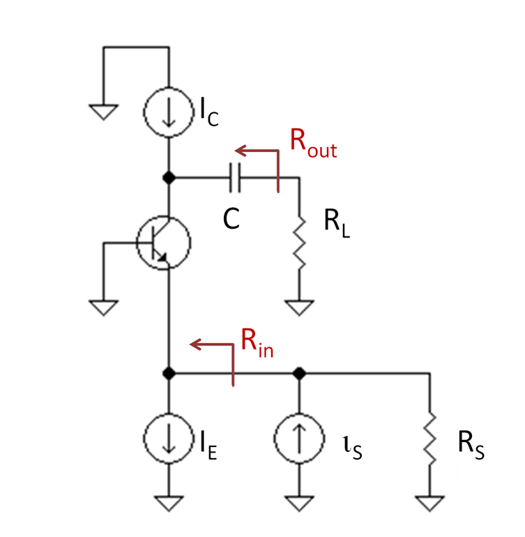
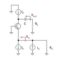 Figure 6: Bipolar current follower biased by current source IE and with active load IC
Figure 6 shows a bipolar current buffer biased with a current source (designated IE for DC emitter current) and driving another DC current source as active load (designated IC for DC collector current). The AC input signal current iin is applied to the emitter node of the transistor by an AC Norton current source with Norton resistance RS. The AC output current iout is delivered by the buffer via a large coupling capacitor to load RL. This coupling capacitor is large enough to be a short-circuit at frequencies of interest.
Because the transistor output resistance connects input and output sides of the circuit, there is a (very small) backward voltage feedback from the output to the input so this circuit is not unilateral. In addition, for the same reason, the input resistance depends (slightly) upon the output load resistance, and the output resistance depends significantly on the input driver resistance. For more detail see the article on common base amplifier.
See also
External links
Categories:- Electronic amplifiers
-


Wikimedia Foundation. 2010.