- Magnetic detector
-
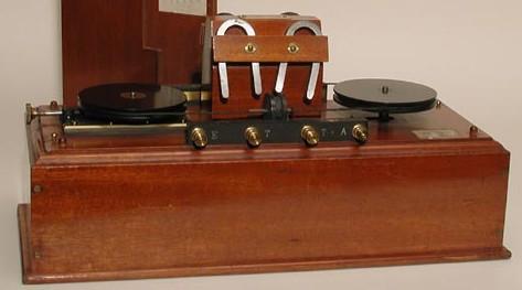
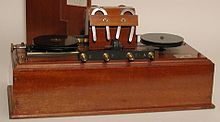 1902 - 1918: Marconi's Wireless Magnetic Detector (London)
The magnetic detector was one of the first practical devices able to make radio signals audible through a pair of headphones. It was not as sensitive as some detectors but despite that, it was favored for early maritime use because of its reliability.
Contents
History
During his transatlantic radio communication experiments in December 1902 Marconi found the coherer to be too unreliable/insensitive for detecting the very weak signals inherent in long distance transmissions. It was this need that drove him to develop the "Maggie" or magnetic detector.
The earliest development models and earliest patent of the magnetic detector had a rotating magnet above a stationary segment of iron band with coils on it. It was based on the theory of operation proposed by Rutherford[1] in 1896 (Phil. Trans. Roy. Soc. London A V. 189, pp. 1—24 [1897]). Further developments by Marconi, et al. resulted in a more effective configuration with the moving iron band driven by a clockwork motor and stationary coils.
Sir John Ambrose Fleming[2] writes in The principles of electric wave telegraphy[3] and telephony:
- It was well known long before the middle of the last century that the discharge of a Leyden jar had a magnetizing power. Sir Humphry Davy magnetized sewing-needles with Leyden jar discharges in 1821. Joseph Henry, in the United States, between 1842 and 1850, explored many of the puzzling facts connected with this subject, and only obtained a clue to the anomalies when he realized that the discharge of a condenser through a low resistance circuit is oscillatory in nature. Amongst other things, Henry noticed the power of condenser discharges to induce secondary currents which could magnetize steel needles even when a great distance separated the primary and secondary circuits. He employed this magnetization to test the direction of the secondary currents, and he was followed in the same field of research by Abria, Marianini, Riess, and Matteucci.
- In 1870 Lord Rayleigh, in discussing some electromagnetic phenomena, pointed out that the resultant magnetic effect of an oscillatory discharge depends upon the direction of the maximum value of the current during the oscillation, and also that there may be superimposed magnetic effects in the same needle.
- In 1895 the subject was again taken up by Professor E. Rutherford, and in a very able paper, published in 1896, he described experiments he had made on the subject.
How it works
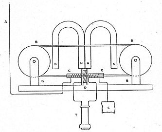 A, Antenna Wire; E, Ground-plate; B B ..., Iron band around pulleys; S N ..., Permanent magnets; C C, RF excitation winding on glass tube through which the iron band travels; D, Audio pickup winding; T, Telephone receiver.
The Marconi version consisted of an endless iron band built up of 70 strands of number 40 gage silk-covered iron wire. In operation, the band passes over two grooved pulleys rotated by a wind-up clockwork motor. The iron band passes through the center of glass tube which is close wound with a single layer along several millimeters with number 36 gage silk-covered copper wire. This coil functions as the radio frequency excitation coil. Over this winding is a small bobbin wound with wire of the same gauge to a resistance of about 140 ohms. This coil functions as the audio pickup coil. Around these coils two weak permanent horseshoe magnets are arranged to magnetize the iron band as it passes through the glass tube.
The magnet poles are arranged to create two opposite magnetic fields each directed toward (or away) from the center of the coils in opposite directions along the wire. This functions to magnetize the iron band first in one direction as it approaches the center of the coils, then reverse its magnetism to the opposite direction as it leaves from the other side of the coil. This causes a reversal of the iron band’s magnetism just as it passes through the coils. This continuous reversal in magnetism induces a very weak DC current in the audio pickup coil.
The radio signal from the antenna is tuned and passed through the excitation coil, the other end of which is connected to ground. That radio signal in the excitation coil aids the reversal of the magnetization of the iron band as it passes under the audio pickup coil. This works by agitating the magnetic domains to reduce reluctance in the iron band. Changes in the amplitude of the radio signal change the rate of magnetic reversal in the moving iron band. This causes variation in the magnetic flux through the audio pickup coil causing the current in the audio pickup coil to vary. The audio pickup coil is connected to a telephone receiver which converts the varying current to sound.
From a technical standpoint, several subtle prerequisites are necessary for operation. The strength of the magnetic field of the permanent magnets at the iron band must be of the same order of magnitude as the strength of the field generated by the radio frequency excitation coil, allowing the radio frequency signal to significantly contribute to the total the magnetic field. Also, the radio signal applied to the excitation coil roughly matches the impedance of the excitation coil which is very low and requires a special tuner design considerations. The impedance of the telephone earphone must roughly match the impedance of the audio pickup coil, which is a few hundred ohms. The iron band moves a few millimeters per second. Its sensitivity does not approach that of a good mineral detector, yet it is a reliable and surprisingly sensitive detector for radio.
Marconi Company usage
The "Maggie" was the "official" detector used by the Marconi Company in 1902 through 1918, although it was soon supplanted by crystal receivers and multi-element vacuum tubes.
Maintenance
In the Handbook Of Technical Instruction For Wireless Telegraphists by: J. C. Hawkhead (Second Edition Revised by H. M. Dowsett) on pp 175 are detailed instructions and specifications for operation and maintenance of the Marconi's Wireless magnetic detector.
References
- ^ E. Rutherford: "A Magnetic Detector of Electrical Waves and some of its Applications" Communicated by J. J. Thomson, Philosophical Transactions of the Royal Society of London, June 18, 1896
- ^ In 1899 Fleming became Scientific Advisor to the Marconi Company and soon after began work on the designing the power plant to enable the Marconi Company to transmit across the Atlantic John Ambrose Fleming
- ^ The principles of electric wave telegraphy and telephony By Sir John Ambrose Fleming; pp 386 [1]
External links
- The Marconi magnetic detector From the book "A Handbook of Wireless Telegraphy" (1913) by J. Erskine-Murray. D.Sc.
Categories:- History of radio
- Radio electronics
- Detectors

Wikimedia Foundation. 2010.