- Optical tweezers
-
Optical tweezers (originally called "single-beam gradient force trap") are scientific instruments that use a highly focused laser beam to provide an attractive or repulsive force (typically on the order of piconewtons), depending on the refractive index mismatch to physically hold and move microscopic dielectric objects. Optical tweezers have been particularly successful in studying a variety of biological systems in recent years.
History and development
The detection of optical scattering and gradient forces on micrometer sized particles was first reported in 1970 by Arthur Ashkin, a scientist working at Bell Labs.[1] Years later, Ashkin and colleagues reported the first observation of what is now commonly referred to as an optical tweezers: a tightly focused beam of light capable of holding microscopic particles stable in three dimensions.[2]
One of the authors of this seminal 1986 paper, United States Secretary of Energy Steven Chu, would go on to use optical tweezing in his work on cooling and trapping neutral atoms.[3] This research earned Chu the 1997 Nobel Prize in Physics along with Claude Cohen-Tannoudji and William D. Phillips.[4] In an interview, Steven Chu described how Ashkin had first envisioned optical tweezing as a method for trapping atoms.[5] Ashkin was able to trap larger particles (10 to 10,000 nanometers in diameter) but it fell to Chu to extend these techniques to the trapping of neutral atoms (0.1 nanometers in diameter) utilizing resonant laser light and a magnetic gradient trap (cf. Magneto-optical trap).
In the late 1980s, Arthur Ashkin and Joseph M. Dziedzic demonstrated the first application of the technology to the biological sciences, using it to trap an individual tobacco mosaic virus and Escherichia coli bacterium.[6] Throughout the 1990s and afterwards, researchers like Carlos Bustamante, James Spudich, and Steven Block pioneered the use of optical trap force spectroscopy to characterize molecular-scale biological motors. These molecular motors are ubiquitous in biology, and are responsible for locomotion and mechanical action within the cell. Optical traps allowed these biophysicists to observe the forces and dynamics of nanoscale motors at the single-molecule level; optical trap force-spectroscopy has since led to greater understanding of the stochastic nature of these force-generating molecules.
Optical tweezers have proven useful in other areas of biology as well. For instance, in 2003 the techniques of optical tweezers were applied in the field of cell sorting; by creating a large optical intensity pattern over the sample area, cells can be sorted by their intrinsic optical characteristics.[7][8] Optical tweezers have also been used to probe the cytoskeleton, measure the visco-elastic properties of biopolymers, and study cell motility.
Researchers have also worked to convert optical tweezers from large, complex instruments to smaller, simpler ones, for use by those with smaller research budgets.[3][9]
Physics of optical tweezers
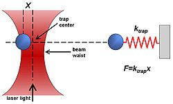 Dielectric objects are attracted to the center of the beam, slightly above the beam waist, as described in the text. The force applied on the object depends linearly on its displacement from the trap center just as with a simple spring system.
General description
Optical tweezers are capable of manipulating nanometer and micrometer-sized dielectric particles by exerting extremely small forces via a highly focused laser beam. The beam is typically focused by sending it through a microscope objective. The narrowest point of the focused beam, known as the beam waist, contains a very strong electric field gradient. It turns out that dielectric particles are attracted along the gradient to the region of strongest electric field, which is the center of the beam. The laser light also tends to apply a force on particles in the beam along the direction of beam propagation. It is easy to understand why if one considers light to be a group of particles, each impinging on the tiny dielectric particle in its path. This is known as the scattering force and results in the particle being displaced slightly downstream from the exact position of the beam waist, as seen in the figure.
Optical traps are very sensitive instruments and are capable of the manipulation and detection of sub-nanometer displacements for sub-micrometre dielectric particles.[10] For this reason, they are often used to manipulate and study single molecules by interacting with a bead that has been attached to that molecule. DNA and the proteins and enzymes that interact with it are commonly studied in this way.
For quantitative scientific measurements, most optical traps are operated in such a way that the dielectric particle rarely moves far from the trap center. The reason for this is that the force applied to the particle is linear with respect to its displacement from the center of the trap as long as the displacement is small. In this way, an optical trap can be compared to a simple spring, which follows Hooke's law.
Detailed view of optical tweezers
Proper explanation of optical trapping behavior depends upon the size of the trapped particle relative to the wavelength of light used to trap it. In cases where the dimensions of the particle are much greater than the wavelength, a simple ray optics treatment is sufficient. If the wavelength of light far exceeds the particle dimensions, the particles can be treated as electric dipoles in an electric field. For optical trapping of dielectric objects of dimensions within an order of magnitude of the trapping beam wavelength, the only accurate models involve the treatment of either time dependent or time harmonic maxwell equations using appropriate boundary conditions.
The ray optics approach
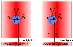 Ray optics explanation (unfocused laser). When the bead is displaced from the beam center (right image), the larger momentum change of the more intense rays cause a net force to be applied back toward the center of the laser. When the bead is laterally centered on the beam (left image), the resulting lateral force is zero. But an unfocused laser still causes a force pointing away from the laser.
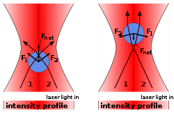 Ray optics explanation (focused laser). In addition to keeping the bead in the center of the laser, a focused laser also keeps the bead in a fixed axial position: The momentum change of the focused rays causes a force towards the laser focus, both when the bead is in front (left image) or behind (right image) the laser focus. So, bead will stay slightly behind the focus, where this force compensates the scattering force.
In cases where the diameter of a trapped particle is significantly greater than the wavelength of light, the trapping phenomenon can be explained using ray optics. As shown in the figure, individual rays of light emitted from the laser will be refracted as it enters and exits the dielectric bead. As a result, the ray will exit in a direction different from which it originated. Since light has a momentum associated with it, this change in direction indicates that its momentum has changed. Due to Newton's third law, there should be an equal and opposite momentum change on the particle.
Most optical traps operate with a Gaussian beam (TEM00 mode) profile intensity. In this case, if the particle is displaced from the center of the beam, as in the right part of the figure, the particle has a net force returning it to the center of the trap because more intense beams impart a larger momentum change towards the center of the trap than less intense beams, which impart a smaller momentum change away from the trap center. The net momentum change, or force, returns the particle to the trap center.
If the particle is located at the center of the beam, then individual rays of light are refracting through the particle symmetrically, resulting in no net lateral force. The net force in this case is along the axial direction of the trap, which cancels out the scattering force of the laser light. The cancellation of this axial gradient force with the scattering force is what causes the bead to be stably trapped slightly downstream of the beam waist.
The standard tweezers works with the trapping laser propagated in the direction of gravity [11] and the inverted tweezers works against gravity.
The electric dipole approximation
In cases where the diameter of a trapped particle is significantly smaller than the wavelength of light, the conditions for Rayleigh scattering are satisfied and the particle can be treated as a point dipole in an inhomogenous electromagnetic field. The force applied on a single charge in an electromagnetic field is known as the Lorentz force,
The force on the dipole can be calculated by substituting two terms for the electric field in the equation above, one for each charge. The polarization of a dipole is
 where
where  is the distance between the two charges. For a point dipole, the distance is infinitesimal,
  Taking into account that the two charges have opposite signs, the force takes the form
Notice that the
 cancel out. Multiplying through by the charge, q, converts position,
  , into polarization,
  ,
,where in the second equality, it has been assumed that the dielectric particle is linear (i.e.
 ).
).In the final steps, two equalities will be used: (1) A Vector Analysis Equality, (2) One of Maxwell's Equations.
First, the vector equality will be inserted for the first term in the force equation above. Maxwell's equation will be substituted in for the second term in the vector equality. Then the two terms which contain time derivatives can be combined into a single term.[12]
The second term in the last equality is the time derivative of a quantity that is related through a multiplicative constant to the Poynting vector, which describes the power per unit area passing through a surface. Since the power of the laser is constant when sampling over frequencies much shorter than the frequency of the laser's light ~1014 Hz, the derivative of this term averages to zero and the force can be written as
The square of the magnitude of the electric field is equal to the intensity of the beam as a function of position. Therefore, the result indicates that the force on the dielectric particle, when treated as a point dipole, is proportional to the gradient along the intensity of the beam. In other words, the gradient force described here tends to attract the particle to the region of highest intensity. In reality, the scattering force of the light works against the gradient force in the axial direction of the trap, resulting in an equilibrium position that is displaced slightly downstream of the intensity maximum. Under the Rayleigh approximation, we can write the scattering force as[13]
Since the scattering is isotropic, the net momentum is transferred in the forward direction. On the quantum level, we picture this as incident photons all traveling in the forward direction and being scattered isotropically. By conservation of momentum, the sphere must accumulate the photons' original momenta, causing a forward force.
Experimental design, construction and operation
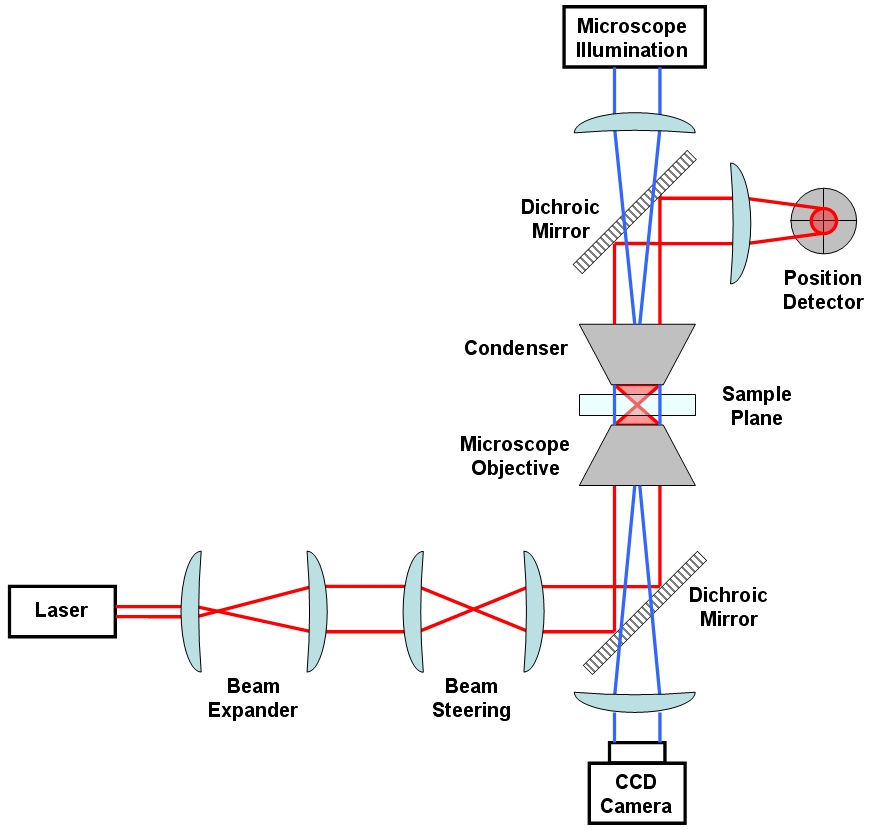
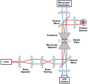 A generic optical tweezer diagram with only the most basic components.
The most basic optical tweezer setup will likely include the following components: a laser (usually Nd:YAG), a beam expander, some optics used to steer the beam location in the sample plane, a microscope objective and condenser to create the trap in the sample plane, a position detector (e.g. quadrant photodiode) to measure beam displacements and a microscope illumination source coupled to a CCD camera.
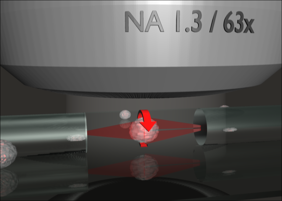
An Nd:YAG laser (1064 nm wavelength) is a common choice of laser for working with biological specimens. This is because such specimens (being mostly water) have a low absorption coefficient at this wavelength.[14] A low absorption is advisable so as to minimise damage to the biological material, sometimes referred to as opticution. Perhaps the most important consideration in optical tweezer design is the choice of the objective. A stable trap requires that the gradient force, which is dependent upon the numerical aperture (NA) of the objective, be greater than the scattering force. Suitable objectives typically have an NA between 1.2 and 1.4.[15]
While alternatives are available, perhaps the simplest method for position detection involves imaging the trapping laser exiting the sample chamber onto a quadrant photodiode. Lateral deflections of the beam are measured similarly to how it is done using atomic force microscopy (AFM).
Expanding the beam emitted from the laser to fill the aperture of the objective will result in a tighter, diffraction-limited spot.[16] While lateral translation of the trap relative to the sample can be accomplished by translation of the microscope slide, most tweezer setups have additional optics designed to translate the beam to give an extra degree of translational freedom. This can be done by translating the first of the two lenses labelled as "Beam Steering" in the figure. For example, translation of that lens in the lateral plane will result in a laterally deflected beam from what is drawn in the figure. If the distance between the beam steering lenses and the objective are chosen properly, this will correspond to a similar deflection before entering the objective and a resulting lateral translation in the sample plane. The position of the beam waist, that is the focus of the optical trap, can be adjusted by an axial displacement of the initial lens. Such an axial displacement causes the beam to diverge or converge slightly, the end result of which is an axially displaced position of the beam waist in the sample chamber.[17]
Visualization of the sample plane is usually accomplished through illumination via a separate light source coupled into the optical path in the opposite direction using dichroic mirrors. This light is incident on a CCD camera and can be viewed on an external monitor or used for tracking the trapped particle position via video tracking.
Descriptions of various optical tweezer setups
Optical tweezers based on alternate laser beam modes
The majority of optical tweezers make use of conventional TEM00 Gaussian beams. However a number of other beam types have been used to trap particles, including high order laser beams i.e. Hermite Gaussian beam (TEMxy), Laguerre-Gaussian (LG) beams (TEMpl) and Bessel beams.
Optical tweezers based on Laguerre-Gaussian beams have the unique capability of trapping particles that are optically reflective and absorptive. Laguerre-Gaussian beams also possess a well-defined orbital angular momentum that can rotate particles.[18][19] This is accomplished without external mechanical or electrical steering of the beam.
Both zero and higher order Bessel Beams also possess a unique tweezing ability. They can trap and rotate multiple particles that are millimeters apart and even around obstacles.[20]
Micromachines can be driven by these unique optical beams due to their intrinsic rotating mechanism due to the spin and orbital angular momentum of light. [21]
Multiplexed optical tweezers
A typical setup uses one laser to create one or two traps. More complex optical tweezing operations can be achieved either by time-sharing a single laser beam among several optical tweezers or by diffractively splitting the beam into multiple traps. With acousto-optic deflectors or galvanometer-driven mirrors, a single laser beam can be shared among hundreds of optical tweezers in the focal plane, or else spread into an extended one-dimensional trap. Specially designed diffractive optical elements can divide a single input beam into hundreds of continuously illuminated traps in arbitrary three-dimensional configurations. The trap-forming hologram also can specify the mode structure of each trap individually, thereby creating arrays of optical vortices, optical tweezers, and holographic line traps, for example. When implemented with a spatial light modulator, such holographic optical traps also can move objects in three dimensions.
Optical traps based on single mode optical fibers
The standard fiber optical trap relies on the same principle as the optical trapping, but with the Gaussian laser beam delivered through an Optical fiber. If one end of the optical fiber is moulded into a lens-like facet, the nearly gaussian beam carried by a single mode standard fiber will be focussed at some distance from the fiber tip. The effective Numerical Aperture of such assembly is usually not enough to allow for a full 3D optical trap but only for a 2D trap (optical trapping and manipulation of objects will be possible only when, e.g., they are in contact with a surface ).[22] A true 3D optical trapping based on a single fiber, with a trapping point which is not in nearly contact with the fiber tip, has been realized based on a not-standard annular-core fiber arrangement and a total-internal-reflection geometry.[23]
On the other hand, if the ends of the fiber are not moulded, the laser exiting the fiber will be diverging and thus a stable optical trap can only be realised by balancing the gradient and the scattering force from two opposing ends of the fiber. The gradient force will trap the particles the transverse direction, while the axial optical force comes from the scattering force of the two counter propagating beams emerging from the two fibers. The equilibrium z-position of such a trapped bead is where the two scattering forces equal each other. This work was pioneered by A. Constable et al., Opt. Lett. 18,1867 (1993), and followed by J.Guck et al., Phys. Rev. Lett. 84, 5451 (2000), who made use of this technique to stretch microparticles. By manipulating the input power into the two ends of the fiber, there will be an increase of a "optical stretching" that can be used to measure viscoelastic properties of cells, with sensitivity sufficient to distinguish between different individual cytoskeletal phenotypes. i.e. human erythrocytes and mouse fibroblasts. A recent test has seen great success in differentiating cancerous cells from non-cancerous ones from the two opposed, non-focused laser beams.[24]
Multimode fiber-based traps for advanced manipulation
 The Optical Cell Rotator is a fiber based laser trap that can hold and precisely orient living cells for tomographic microscopy.
While earlier version of fiber-based laser traps exclusively used single mode beams, M. Kreysing and colleagues recently showed that the careful excitation of further optical modes in a short piece of optical fiber allows the realization of non-trivial trapping geometries. By this the researchers were able to orient various human cell types (individual cells and clusters) on a microscope. The main advantage of the so-called "optical cell rotator" technology over standard optical tweezers is the decoupling of trapping from imaging optics. This, its modular design, and the high compatibility of divergent laser traps with biological material indicates the great potential of this new generation of laser traps in medical research and life science.[25]
Optical tweezers in a 'landscape' (cell sorting)
One of the more common cell-sorting systems makes use of flow cytometry through fluorescent imaging. In this method, a suspension of biologic cells is sorted into two or more containers, based upon specific fluorescent characteristics of each cell during an assisted flow. By using an electrical charge that the cell is "trapped" in, the cells are then sorted based on the fluorescence intensity measurements. The sorting process is undertaken by an electrostatic deflection system that diverts cells into containers based upon their charge.
In the optically actuated sorting process, the cells are flowed through into an optical landscape i.e. 2D or 3D optical lattices. Without any induced electrical charge, the cells would sort based on their intrinsic refractive index properties and can be re-configurability for dynamic sorting. An optical lattice can be created using diffractive optics and optical elements.[7]
On the other hand, K. Ladavac et al. used a spatial light modulator to project an intensity pattern to enable the optical sorting process.[26] K. Xiao and D. G. Grier applied holographic video microscopy to demonstrate that this technique can sort colloidal spheres with part-per-thousand resolution for size and refractive index.[27]
The main mechanism for sorting is the arrangement of the optical lattice points. As the cell flow through the optical lattice, there are forces due to the particles drag force that is competing directly with the optical gradient force (See Physics of optical tweezers) from the optical lattice point. By shifting the arrangement of the optical lattice point, there is a preferred optical path where the optical forces are dominant and biased. With the aid of the flow of the cells, there is a resultant force that is directed along that preferred optical path. Hence, there is a relationship of the flow rate with the optical gradient force. By adjusting the two forces, one will be able to obtain a good optical sorting efficiency.
Competition of the forces in the sorting environment need fine tuning to succeed in high efficient optical sorting. The need is mainly with regards to the balance of the forces; drag force due to fluid flow and optical gradient force due to arrangement of intensity spot.
Scientists at the University of St. Andrews have received considerable funding from the UK Engineering and Physical Sciences Research Council (EPSRC) for an optical sorting machine. This new technology could rival the conventional fluorescence-activated cell sorting.[28]
Optical tweezers based on evanescent fields
An evanescent field [29] is a residue optical field that "leaks" during total internal reflection. This "leaking" of light fades off at an exponential rate. The evanescent field has found a number of applications in nanometer resolution imaging (microscopy); optical micromanipulation (optical tweezers) are becoming ever more relevant in research.
In optical tweezers, a continuous evanescent field can be created when light is propagating through an optical waveguide (multiple total internal reflection). The resulting evanescent field has a directional sense and will propel microparticles along its propagating path. This work was first pioneered by S. Kawata and T. Sugiura, in 1992, who showed that the field can be coupled to the particles in proximity on the order of 100 nanometers.[30]
This direct coupling of the field is treated as a type of photon tunnelling across the gap from prism to microparticles. The result is a directional optical propelling force.
A recent updated version of the evanescent field optical tweezers makes use of extended optical landscape patterns to simultaneously guide a large number of particles into a preferred direction without using a waveguide. It is termed as Lensless Optical Trapping (“LOT”). The orderly movement of the particles is aided by the introduction of Ronchi Ruling that creates well-defined optical potential wells (replacing the waveguide). This means that particles are propelled by the evanescent field while being trapped by the linear bright fringes. At the moment, there are scientists working on focused evanescent fields as well.
Another approach that has been recently proposed makes use of surface plasmons, which is an enhanced evanescent wave localized at a metal/dielectric interface. The enhanced force field experienced by colloidal particles exposed to surface plasmons at a flat metal/dielectric interface has been for the first time measured using a photonic force microscope, the total force magnitude being found 40 times stronger compared to a normal evanescent wave.[31] By patterning the surface with gold microscopic islands it is possible to have selective and parallel trapping in these islands. The forces of the latter optical tweezers lie in the femtonewton range.[32]
Optical tweezers: an indirect approach
Ming Wu, a UC Berkeley Professor of electrical engineering and computer sciences invented the new optoelectronic tweezers.
Wu transformed the optical energy from low powered light emitting diodes (LED) into electrical energy via a photoconductive surface. The idea is to allow the LED to switch on and off the photoconductive material via its fine projection. As the optical pattern can be easily transformable through optical projection, this method allows a high flexibility of switching different optical landscapes.
The manipulation/tweezing process is done by the variations between the electric field actuated by the light pattern. The particles will be either attracted or repelled from the actuated point due to the its induced electrical dipole. Particles suspended in a liquid will be susceptible to the electrical field gradient, this is known as dielectrophoresis.
One clear advantage is that the electrical conductivity is different between different kinds of cells. Living cells have a lower conductive medium while the dead ones have minimum or no conductive medium. The system may be able to manipulate roughly 10,000 cells or particles at the same time.
See comments by Professor Kishan Dholakia on this new technique, K. Dholakia, Nature Materials 4, 579–580 (01 Aug 2005) News and Views.
"The system was able to move live E. coli bacteria and 20-micrometre-wide particles, using an optical power output of less than 10 microwatts. This is one-hundred-thousandth of the power needed for [direct] optical tweezers".[33]
Optical binding
When a cluster of microparticles are trapped within a monochromatic laser beam, the organization of the microparticles within the optical trapping is heavily dependent on the redistributing of the optical trapping forces amongst the microparticles. This redistribution of light forces amongst the cluster microparticles provides a new force equilibrium on the cluster as a whole. As such we can say that the cluster of microparticles are somewhat bound together by light. One of the first evidence of optical binding was reported by Michael M. Burns, Jean-Marc Fournier, and Jene A. Golovchenko .[34]
See also
- Tweezers, the mechanical device from which optical tweezers take their name
References
- ^ Ashkin, A. (1970). "Acceleration and Trapping of Particles by Radiation Pressure". Phys. Rev. Lett. 24 (4): 156–159. Bibcode 1970PhRvL..24..156A. doi:10.1103/PhysRevLett.24.156.
- ^ Ashkin A, Dziedzic JM, Bjorkholm JE, Chu S (1986). "Observation of a single-beam gradient force optical trap for dielectric particles". Opt. Lett. 11 (5): 288–290. Bibcode 1986OptL...11..288A. doi:10.1364/OL.11.000288.
- ^ a b Matthews J.N.A. (2009). "Commercial optical traps emerge from biophysics labs". Physics Today: 26. http://ptonline.aip.org/journals/doc/PHTOAD-ft/vol_62/iss_2/26_1.shtml.
- ^ Hill, Murray (November 1987). "He wrote the book on atom trapping". Retrieved June 25, 2005.
Interview conducted for internal newsletter at Bell Labs. Contains confirmation of Ashkin as the inventor of optical trapping and provides information on the 1997 Nobel Prize in Physics. - ^ "Conversations with History: An Interview with Steven Chu" (2004), Institute of International Studies, UC Berkeley. Last accessed on September 2, 2006.
- ^ Ashkin A, Dziedzic JM (1987). "Optical trapping and manipulation of viruses and bacteria". Science 235 (4795): 1517–1520. doi:10.1126/science.3547653. PMID 3547653.
- ^ a b MacDonald MP, Spalding GC, Dholakia K (2003). "Microfluidic sorting in an optical lattice". Nature 426 (6965): 421–424. Bibcode 2003Natur.426..421M. doi:10.1038/nature02144. PMID 14647376.
- ^ Koss BA, Grier DG, "Optical Peristalsis"
- ^ Applegate, Jr. R. W. et al. (2004). "Optical trapping, manipulation, and sorting of cells and colloids in microfluidic systems with diode laser bars". Optics Express 12 (19): 4390–8. Bibcode 2004OExpr..12.4390A. doi:10.1364/OPEX.12.004390. PMID 19483988.
- ^ Moffitt JR, Chemla YR, Izhaky D, Bustamante C (2006). "Differential detection of dual traps improves the spatial resolution of optical tweezers". Proc. Natl. Acad. Sci. U.S.A. 103 (24): 9006–9011. Bibcode 2006PNAS..103.9006M. doi:10.1073/pnas.0603342103. PMC 1482556. PMID 16751267. http://www.pubmedcentral.nih.gov/articlerender.fcgi?tool=pmcentrez&artid=1482556.
- ^ Lynn Paterson "Novel micromanipulation techniques in optical tweezers", (2003)
- ^ Gordon JP (1973). "Radiation Forces and Momenta in Dielectric Media". Physical Review A 8 (1): 14–21. Bibcode 1973PhRvA...8...14G. doi:10.1103/PhysRevA.8.14.
- ^ Harada Y, Asakura T (1996). "Radiation Forces on a dielectric sphere in the Rayleigh Scattering Regime". Optics Communications 124 (5–6): 529–541. Bibcode 1996OptCo.124..529H. doi:10.1016/0030-4018(95)00753-9.
- ^ D. J. Stevenson; T. K. Lake; B. Agate; V. Gárcés-Chávez; K. Dholakia; F. Gunn-Moore (2006-10-16). "Optically guided neuronal growth at near infrared wavelengths". Optics Express 14 (21): 9786–93. Bibcode 2006OExpr..14.9786S. doi:10.1364/OE.14.009786. PMC 2869025. PMID 19529370. http://www.opticsinfobase.org/viewmedia.cfm?uri=oe-14-21-9786&seq=0.
- ^ Neuman KC, Block SM (2004). "Optical trapping". Review of Scientific Instruments 75 (9): 2787–809. Bibcode 2004RScI...75.2787N. doi:10.1063/1.1785844. PMC 1523313. PMID 16878180. http://www.pubmedcentral.nih.gov/articlerender.fcgi?tool=pmcentrez&artid=1523313.
- ^ Svoboda K, Block SM (1994). "Biological Application of Optical Forces". Annual Reviews of Biophysics and Biomolecular Structure 23: 247–285. doi:10.1146/annurev.bb.23.060194.001335.
- ^ Shaevitz JW, "A Practical Guide to Optical Trapping" (August 22, 2006). Last accessed on September 12, 2006.
- ^ Curtis JE, Grier DG, "Structure of Optical Vortices" (2003). Last accessed on September 3, 2006.
- ^ Padgett M, "Optical Spanners". Last accessed on September 3, 2006.
- ^ McGloin D, Garces-Chavez V, Paterson L, Carruthers T, Melvil H, Dholakia K, "Bessel Beams". Last accessed on September 3, 2006.
- ^ Ladavac K, Grier DG (2004). "Microoptomechanical pump assembled and driven by holographic optical vortex arrays". Optics Express 12 (6): 1144–9. arXiv:cond-mat/0402634. Bibcode 2004OExpr..12.1144L. doi:10.1364/OPEX.12.001144. PMID 19474932.
- ^ Hu Z, Wang J, Liang J (2004). "Manipulation and arrangement of biological and dielectric particles by a lensed fiber probe". Optics Express 12 (17): 4123–8. Bibcode 2004OExpr..12.4123H. doi:10.1364/OPEX.12.004123. PMID 19483954.
- ^ Liberale C, Minzioni P, Bragheri F, De Angelis F, Di Fabrizio E, Cristiani I (2007). "Miniaturized all-fibre probe for three-dimensional optical trapping and manipulation". Nature Photonics 1 (12): 723–727. Bibcode 2007NaPho...1..723L. doi:10.1038/nphoton.2007.230.
- ^ Jochen Guck, Stefan Schinkinger, Bryan Lincoln, Falk Wottawah, Susanne Ebert, Maren Romeyke, Dominik Lenz, Harold M. Erickson, Revathi Ananthakrishnan, Daniel Mitchell, Josef Käs, Sydney Ulvick and Curt Bilby (2005). "Optical Deformability as an Inherent Cell Marker for Testing Malignant Transformation and Metastatic Competence". Biophys. J. 88 (5): 3689–3698. Bibcode 2005BpJ....88.3689G. doi:10.1529/biophysj.104.045476. PMC 1305515. PMID 15722433. http://www.biophysj.org/cgi/content/full/88/5/3689.
- ^ Moritz Kreysing, Tobias Kießling, Anatol Fritsch, Christian Dietrich, Jochen Guck and Josef Käs (2008). "The optical cell rotator". Opt. Express 16 (21): 16984–92. Bibcode 2008OExpr..1616984K. doi:10.1364/OE.16.016984. PMID 18852807.
- ^ Ladavac, K.; Kasza, K.; Grier, D. (2004). "Sorting mesoscopic objects with periodic potential landscapes: Optical fractionation". Physical Review E 70: 010901. Bibcode 2004PhRvE..70a0901L. doi:10.1103/PhysRevE.70.010901.
- ^ Xiao, Ke; Grier, David G. (2010). "Multidimensional Optical Fractionation of Colloidal Particles with Holographic Verification". Physical Review Letters 104 (2): 028302. Bibcode 2010PhRvL.104b8302X. doi:10.1103/PhysRevLett.104.028302. PMID 20366628.
- ^ "Optical fractionation and sorting.", IRC Scotland. Last accessed on September 3, 2006.
- ^ Evanescent Field Polarization and Intensity Profiles
- ^ Kawata, S; Sugiura, T (1992). "Movement of micrometer-sized particles in the evanescent field of a laser beam". Optics letters 17 (11): 772–4. Bibcode 1992OptL...17..772K. doi:10.1364/OL.17.000772. PMID 19794626.
- ^ Volpe G, Quidant R, Badenes G, Petrov D (2006). "Surface Plasmon Radiation Forces". Phys. Rev. Lett. 96 (23): 238101. Bibcode 2006PhRvL..96w8101V. doi:10.1103/PhysRevLett.96.238101. PMID 16803408.
- ^ Righini M, Volpe G, Girard C, Petrov D, Quidant R (2008). "Surface Plasmon Optical Tweezers: Tunable Optical Manipulation in the Femtonewton Range". Phys. Rev. Lett. 100 (18): 186804. Bibcode 2008PhRvL.100r6804R. doi:10.1103/PhysRevLett.100.186804. PMID 18518404.
- ^ Invention: Soldiers obeying odours, New Scientist, 8 November 2005
- ^ Burns M.M., Golovchenko J-M., Golovchenko J.A. (1989). "Optical binding". Phys. Rev. Lett. 63 (12): 1233–1236. Bibcode 1989PhRvL..63.1233B. doi:10.1103/PhysRevLett.63.1233. PMID 10040510.
External links
- Links to the worldwide optical trapping community, [1]
- Reviews of optical tweezers
- A. Ashkin, "Optical trapping and manipulation of neutral particles using lasers"[2]
- Neuman, K.C., and Block S.M Review on Optical Trapping method [3]
- M. Lang and S. Block, A Resource Letter on Optical Tweezers [4]
- T. Perkins, Recent review of optical tweezers with biological applications [5]
- K.Dholakia on Recent review of state of the art tweezers [6]
- D. McGloin on Review of Bessel beam optical tweezers [7]
- David Grier on A revolution in optical manipulation [8]
- A more detailed list of references can be obtained from the online manuscript written by Justin E Molloy [9] and Miles J Padgett [10] titled Lights, Action: Optical Tweezers[11] posted online
- Web resources
- What are optical tweezers [12]
- Recent Optical Tweezers Journal Papers [13]
- Open source software for computer generated hologram design [14]
- Four optical traps used to wind two DNA molecules around each other [15]
- Using optical tweezers to play a game of Tetris... [16]
- Single molecule studies using Optical Tweezers & TIRF microscopy [17]
- Optical Tweezers, An Introduction (Stanford University)
- Airborne particle generation for optical tweezers (SPIE Newsroom) [18]
- Multimedia links
- BBC Frontier covering the technique of Optical Tweezers 2003 [19]
- Interactive simulation of OT from PhET at U. Colorado.
- A Java applet to explore the mechanism of linear momentum transfer in optical tweezers [20]
- Movies showing positioning and rotation controlled by optical tweezers [21]
- Videos of optical tweezers being used on bacteria.
- Videos of optical tweezers being used on fungi.
- Video of optical tweezers doing some rudimentary knitting with two DNA molecules (Flash video)
- Video of optical tweezers used to play the tiniest game of Tetris ever (Flash video)
Categories:- Photonics
- Condensed matter physics
- Molecular biology
- Cell biology
- Biophysics
- Optical trapping
- 1986 introductions
- Force lasers
-


![\begin{align}
\mathbf{F} & = \left(\mathbf{p}\cdot\nabla\right)\mathbf{E}+\frac{d\mathbf{p}}{dt}\times\mathbf{B} \\
& = \alpha\left[\left(\mathbf{E}\cdot\nabla\right)\mathbf{E}+\frac{d\mathbf{E}}{dt}\times\mathbf{B}\right], \\
\end{align}](e/00e8fb696cb60b8e2320e30812bbcbe3.png)


![\begin{align}
\mathbf{F} & = \alpha\left[\frac{1}{2}\nabla E^2-\mathbf{E}\times\left(\nabla\times\mathbf{E}\right)+\frac{d\mathbf{E}}{dt}\times\mathbf{B}\right] \\
& = \alpha\left[\frac{1}{2}\nabla E^2-\mathbf{E}\times\left(-\frac{d\mathbf{B}}{dt}\right)+\frac{d\mathbf{E}}{dt}\times\mathbf{B}\right] \\
& = \alpha\left[\frac{1}{2}\nabla E^2+\frac{d}{dt}\left(\mathbf{E}\times\mathbf{B}\right)\right]. \\
\end{align}](7/797318e2024500fa6580b0e5073509e4.png)


Wikimedia Foundation. 2010.