- Orthographic projection
-
Part of a series on: Graphical projection - Parallel projection
- Orthographic projection
- Multiviews
- Plan, or floor plan
- Section
- Elevation
- Auxiliary
- Axonometric projection (i.e. pictorials)
- Isometric projection
- Dimetric projection
- Trimetric projection
- Multiviews
- Oblique projection
- Cavalier projection
- Cabinet projection
- Orthographic projection
- Perspective projection
- Linear perspective
- One-point perspective
- Two-point perspective
- Three-point perspective
- Zero-point perspective
- Curvilinear perspective
- Reverse perspective
- Linear perspective
Views- Bird's-eye view/Aerial view
- Detail view
- 3/4 perspective
- Cutaway drawing
- Exploded view drawing
- Fisheye
- Fixed 3D
- Panorama
- Top-down perspective
- Worm's-eye view
- Zoom
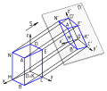
Orthographic projection (or orthogonal projection) is a means of representing a three-dimensional object in two dimensions. It is a form of parallel projection, where all the projection lines are orthogonal to the projection plane,[1] resulting in every plane of the scene appearing in affine transformation on the viewing surface. It is further divided into multiview orthographic projections and axonometric projections. A lens providing an orthographic projection is known as an (object-space) telecentric lens.
The term orthographic is also sometimes reserved specifically for depictions of objects where the axis or plane of the object is also parallel with the projection plane,[1] as in multiview orthographic projections.
 Symbols used to define whether a projection is either Third Angle (right) or First Angle (left).
Contents
Origin
The orthographic projection has been known since antiquity, with its cartographic uses being well documented. Hipparchus used the projection in the 2nd century B.C. to determine the places of star-rise and star-set. In about 14 B.C., Roman engineer Marcus Vitruvius Pollio used the projection to construct sundials and to compute sun positions.[2]
Vitruvius also seems to have devised the term orthographic (from the Greek orthos (= “straight”) and graphē (= “drawing”) for the projection. However, the name analemma, which also meant a sundial showing latitude and longitude, was the common name until François d'Aguilon of Antwerp promoted its present name in 1613.[2]
The earliest surviving maps on the projection appear as woodcut drawings of terrestrial globes of 1509 (anonymous), 1533 and 1551 (Johannes Schöner), and 1524 and 1551 (Apian).[2]
Multiview orthographic projections
Main article: Multiview orthographic projectionWith multiview orthographic projections, up to six pictures of an object are produced, with each projection plane parallel to one of the coordinate axes of the object. The views are positioned relative to each other according to either of two schemes: first-angle or third-angle projection. In each, the appearances of views may be thought of as being projected onto planes that form a 6-sided box around the object. Although six different sides can be drawn, usually three views of a drawing give enough information to make a 3D object. These views are known as front view, top view and right side view.
Pictorials
Main article: Axonometric projectionWithin orthographic projection there is the subcategory known as pictorials. Axonometric pictorials show an image of an object as viewed from a skew direction in order to reveal all three directions (axes) of space in a single picture.[3] Orthographic pictorial instrument drawings are often used to approximate graphical perspective projections, but there is attendant distortion in the approximation. Because pictorial projections inherently have this distortion, in the instrument drawing of pictorials, great liberties may then be taken for economy of effort and best effect. Orthographic pictorials rely on the technique of axonometric projection ("to measure along axes").
See also
References
- ^ a b Maynard, Patric (2005). Drawing distinctions: the varieties of graphic expression. Cornell University Press. pp. 22. ISBN 0801472806. http://books.google.com/?id=4Y_YqOlXoxMC&pg=PA22&lpg=PA22&dq=axonometric+orthographic&q=axonometric%20orthographic.
- ^ a b c Snyder, John P. (1993). Flattening the Earth: Two Thousand Years of Map Projections pp. 16–18. Chicago and London: The University of Chicago Press. ISBN 0-226-76746-9.
- ^ Mitchell, William; Malcolm McCullough (1994). Digital design media. John Wiley and Sons. pp. 169. ISBN 0471286664. http://books.google.com/?id=JrZoGgQEhKkC&pg=PA169&dq=axonometric+orthographic#v=onepage&q=axonometric%20orthographic.
External links

This geometry-related article is a stub. You can help Wikipedia by expanding it. - Parallel projection
