- Photoemission electron microscopy
-
Photoemission Electron microscopy (PEEM, also called photoelectron microscopy, PEM) is a widely used type of emission microscopy. PEEM utilizes local variations in electron emission to generate image contrast. The excitation is usually produced by UV light, synchrotron radiation or X-ray sources. PEEM measures the coefficient indirectly by collecting the emitted secondary electrons generated in the electron cascade that follows the creation of the primary core hole in the absorption process. PEEM is a surface sensitive technique because the emitted electrons originate from a very shallow layer. In physics, this technique is referred to as PEEM, which goes together naturally with low-energy electron diffraction (LEED), and low-energy electron microscopy (LEEM). In biology, it is called photoelectron microscopy (PEM), which fits with photoelectron spectroscopy (PES), transmission electron microscopy (TEM), and scanning electron microscopy (SEM).
Contents
History
Initial development
In 1933, Brüche reported images of cathodes illuminated by UV light. This work was extended by two of his colleagues, H. Mahl and J. Pohl. Brüche made a sketch of his photoelectron emission microscope in his 1933 paper (Figure 1). This is evidently the first photoelectron emission microscope (PEEM).
Improved techniques
In 1963, G. F. Rempfer designed the electron optics for an early ultrahigh-vacuum (UHV) PEEM. In 1965, G. Burroughs at the Night Vision Laboratory, Fort Belvoir, Virginia built the bakeable electrostatic lenses and metal-sealed valves for PEEM. During 1960s, in the PEEM, as well as TEM, the specimens were grounded and could be transferred in the UHV environment to several positions for photocathode formation, processing and observation. These electron microscopes were used for only a brief period of time, but the components live on. The first commercially available PEEM was designed and tested by Engel during the 1960s for his thesis work under E. Ruska and developed it into a marketable product, called the “Metioskop KE3”, by Balzers in 1971. The electron lenses and voltage divider of the PEEM were incorporated into one version of a PEEM for biological studies in Eugene, Oregon around 1970.
Further research
During 1970s and 1980s the second generation (PEEM-2) and third generation (PEEM-3) microscopes were constructed. PEEM-2 is a conventional not aberration-corrected instrument employing electrostatic lenses. It uses a cooled charge-coupled device (CCD) fiber-coupled to a phosphor to detect the electron-optical image. The aberration corrected microscope PEEM-3 employs a curved electron mirror to counter the lowers order aberrations of the electron lenses and the accelerating field.
 Figure 1 Early photoelectron emission microscope of E. Brüche at AEG, Berlin, reproduced from his 1933 paper
Background
Photoelectric effect
The photoemission or photoelectric effect is a quantum electronic phenomenon in which electrons (photoelectrons) are emitted from matter after the absorption of energy from electromagnetic radiation such as UV light or X-ray.
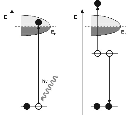
When UV light or X-ray is absorbed by matter, electrons are excited from core levels into unoccupied states, leaving empty core states. Secondary electrons are generated by the decay of the core hole. Auger processes and inelastic electron scattering create a cascade of low-energy electrons. Some electrons penetrate the sample surface and escape into vacuum. A wide spectrum of electrons is emitted with energies between the energy of the illumination and the work function of the sample. This wide electron distribution is the principal source of image aberration in the microscope.
Quantitative analysis
 Figure 2 Photoelectric effect
 Figure 3 Schematic illustration of the photoemission process
Using Einstein’s method, the following equations are used: Energy of photon=Energy needed to remove an electron + Kinetic energy of the emitted electron

h is Planck’s constant;
f is the frequency of the incident photon;
 is the work function;
 is the maximum kinetic energy of ejected electrons;
f0 is the threshold frequency for the photoelectric effect to occur;
m is the rest mass of the ejected electron;
vm is the speed of the ejected electron.
According to Einstein’s special theory of relativity: E (energy) and p (momentum) of a particle is:

m is the rest mass of the particle;
c is the velocity of light.
Electron emission microscopy
This is a type of electron microscopy in which the information carrying beam of electrons originates from the specimen. The source of energy causing the electron emission can be heat (thermionic emission), light (photoelectron emission), ions, or neutral particles, but normally excludes field emission and other methods involving a point source or tip microscopy.
Photoelectron imaging
Photoelectron imaging includes any form of imaging in which the source of information is the distribution of points from which electrons are ejected from the specimen by the action of photons. The technique with the highest resolution photoelectron imaging is presently photoelectron emission microscopy using UV light.
Photoemission Electron Microscope
Photoemission Electron Microscope (PEEM) is a parallel imaging instrument. It creates at any given moment a complete picture of the photoelectron distribution emitted from the imaged surface region.
Light sources
The viewed area of the specimen must be illuminated homogeneously with appropriate radiation (ranging from UV to hard x-rays). UV light is the most common radiation used in PEEM because very bright sources are available, like Hg lamps. However, other wavelengths (like soft x-rays) are preferred where analytical information is required.
Electron optical column and resolution
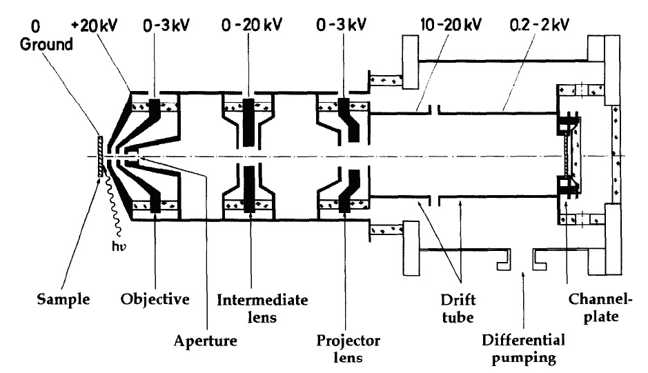
 Figure 4 Scheme of the Photoemission electron microscope
The electron optical column contains two or more electrostatic or magnetic electron lenses, corrector elements such as a stigmator and deflector, an angle-limiting aperture in the backfocal plane of one of the lenses (Figure 4).
As in any emission electron microscope, the objective or cathode lens determines the resolution. The latter is dependent on the electron-optical qualities, such as spherical aberrations, and the energy spread of the photoemitted electrons. The electrons are emitted into the vacuum with an angular distribution close to a cosine square function. A significant velocity component parallel to the surface will decrease the lateral resolution. The faster electrons, leaving the surface exactly along the center line of the PEEM, will also negatively influence the resolution due to the chromatic aberration of the cathode lens. The resolution is inversely proportional to the accelerating field strength at the surface but proportional to the energy spread of the electrons. So resolution r is approximately:

 Figure 5 Typical Photoemission electron microscope
In the equation, d is the distance between the specimen and the objective, ΔE is the distribution width of the initial electron energies and U is the accelerating voltage.
Besides the cathode or objective lens, situated on the left hand side of Figure 4, two more lenses are utilized to create an image of the specimen: an intermediate three-electrode lens is used to vary the total magnification between 100× if the lens is deactivated, and up to 1000× when needed. On the right-hand side of Figure 4 is the projector, a three electrode lens combined with a two-element deceleration lens. The main task of this lens combination is the deceleration of the fast 20 keV electrons to energies for which the channelplate has its highest sensitivity. Such an image intensifier has its best performance for impinging electrons with kinetic energies roughly about 1 keV.
Energy filter
An energy filter can be added to the instrument in order to select the electrons that will contribute to the image. This option is particularly used for analytical applications of the PEEM. By using an energy filter, a PEEM microscope can be seen as imaging UPS or XPS. By using this method, spatially resolved photoemission spectra can be acquired with spatial resolutions on the 100 nm scale and with sub-eV resolution. Using such instrument, one can acquire elemental images with chemical state sensibility or work function maps. Also, since the photoelectron are emitted only at the very surface of the material, surface termination maps can be acquired.
Detector
A detector is placed at the end of electron optical column. Usually, a phosphor screen is used to convert the electron image to a photon image. The choice of phosphor type is governed by resolution considerations. A multichannel plate detector that is imaged by a CCD camera can substitute phosphor screen.
Limitations
- The general limitation of PEEM, which is common with most surface science methods, is that the PEEM operates only under fairly restricted vacuum conditions. Whenever electrons are used to excite a specimen or carry information from its surface there has to be a vacuum with an appropriate mean free path for the electrons.
- The resolution of PEEM is limited to about 10 nm, which results from a spread of the photoelectron emission angle. Angle resolved photoemission spectroscopy (ARPES) is a powerful tool for structure analysis. However, it may be difficult to make angle-resolved and energy-selective PEEM measurements because of a lack of intensity. The availability of synchrotron-radiation light sources can offer exciting possibilities in this regard.
Comparison from other techniques
- Transmission electron microscopy (TEM) and scanning electron microscopy (SEM): PEEM differs from these two microscopies by using an electric accelerating field at the surface of specimen. The specimen is part of the electron-optical system.
- Low-energy electron microscopy (LEEM) and mirror electron microscopy (MEM):These two electron emission microscopy use electron gun supply beams which are directed toward the specimen, decelerated and backscattered from the specimen or reflected just before reaching the specimen. In photoemission electron microscopy (PEEM) the same specimen geometry and immersion lens are used, but the electron guns are omitted.
New PEEM technologies
- Time resolve Photoemission electron microscopy (TR-PEEM): TR-PEEM is well suited for real-time observation of fast processes on surfaces equipped with pulsed synchrotron radiation for illumination.
- Time-of-flight Photoemission electron microscopy (TOF-PEEM): TOF-PEEM is PEEM using an ultrafast gated CCD camera or a time-and space-resolving counting detector for observing fast processes on surfaces.
- Multiphoton Photoemission electron microscopy: Multiphoton PEEM can be employed for the study of localized surface plasmon excitations in nanoclusters or for direct spatial observation of the hot-electron lifetime in structured films using femtosecond lasers.
References
- H. Hopster, H. P. Oepen (2005). Magnetic Microscopy of Nanostructures. Springer ISBN 354040-1865,9783540401865
- James A. Samson, David L. Ederer (1998). Vacuum Ultraviolet Spectroscopy. Academic Press ISBN 0126175608, 9780126175608
- O. H. Griffith, W. Engel. Historical perspective and current trends in emission microscopy, mirror electron microscopy and low-energy electron microscopy. Ultramicroscopy, 36 (1991) 1-28
- Peter Buseck, John Cowley, Leroy Eyring (1992). High-Resolution Transmission Electron Microscopy. Oxford University Press ISBN 0195042751, 9780195042757
- Andrzej Wieckowski, Elena R. Savinova, Constantinos G. Vayenas (2003). Catalysis and Electrocatalysis at Nanoparticle Surfaces. CRC Press ISBN 0824708792, 9780824708795
- Harm Hinrich Rotermund. Imaging of Dynamic Processes on Surface byLight. Surface Science Reports, 29 (1997) 265-364
- E. Bauer, M. Mundschau, W. Sweich, W. Telieps. Surface Studies by Low-energy Electron Microscopy (LEEM) and Conventional UV Photoemission Electron Microscopy (PEEM). Ultramicroscopy, 31 (1989) 49-57
- W. Engel, M. Kordesch, H.H. Rotermund, S. Kubala, A. von Oertzen. A UHV-compatible photoelectron emission microscope for applications in surface science. Ultramicroscopy, 36 (1991) 148-153
- H.H. Rotermund, W. Engel, M. Kordesch, G. Ertl. Imaging of spatio-temporal pattern evolution during carbon monoxide oxidation on platinum. Nature, 343 (1990) 355-357
- H.H. Rotermund, W. Engel, S. Jakubith, A. von Oertzen, G. Ertl. Methods and application of UV photoelectron microscopy in heterogeneous catalysis. Ultramicroscopy, 36 (1991) 164-172
- A. Krasyuk, A. Oselsner, S.A. Nepijko, A. Kuksov, C.M. Schneider, G. Schönhense. Time-resolved photoemission electron microscopy of magnetic field and magnetization changes. Appl. Phys. A., 76 (2003) 863-868
- O. Schmidt, M. Bauer, C. Wiemann, R. Porath, M. Scharte, O. Andreyev, G. Schönhense, M. Aeschlimann. Time-resolved two photon photoemission electron microscopy. Appl. Phys. B., 74, (2002) 223-227
- O. Renault, N. Barrett, A. Bailly, L.F. Zagonel, D. Mariolle, J.C. Cezar, N.B. Brookes, K. Winkler, B. Krömker and D. Funnemann, Energy-filtered XPEEM with NanoESCA using synchrotron and laboratory X-ray sources: Principles and first demonstrated results; Surface Science, Volume 601, Issue 20, 15 October 2007, Pages 4727-4732. doi:10.1016/j.susc.2007.05.061
External links
Categories:- Microscopes


Wikimedia Foundation. 2010.