- Mouse mill motor
-
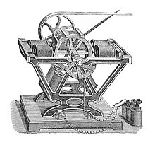 Larger Froment motor, circa 1900
Froment's "mouse mill" motor was an early form of electric motor, also known as the Revolving Armature Engine.[1] It is similar to the contemporary switched reluctance motor and stepper motor, although there is no continuous magnetic circuit between opposed poles.
As the mouse mill motor was simple to construct and its speed could easily be governed, it was later used to drive automatic recorders in telegraphy.
The name derives from the rotor's resemblance to a small treadmill. Their usual size was more to the scale of a hamster than a mouse, but rodents were more common at the time as domestic pests, not domestic pets.
Contents
Construction
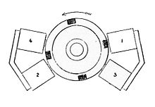 Coils and rotor of a motor
The motor consists of a freely rotating rotor, surrounded by a number of electromagnets. The rotor is made of a light brass wheel, with a number of soft iron bars or "attractors" mounted around its rim and parallel to the axis. There may be one, two or four electromagnets mounted on the frame of the motor, together with a cam-operated switch for each magnet.[2] Many of the early motors were made by the scientific instrument maker Daniel Davis of Boston,[3] who sold them as the "Revolving Armature Engine".
Operation
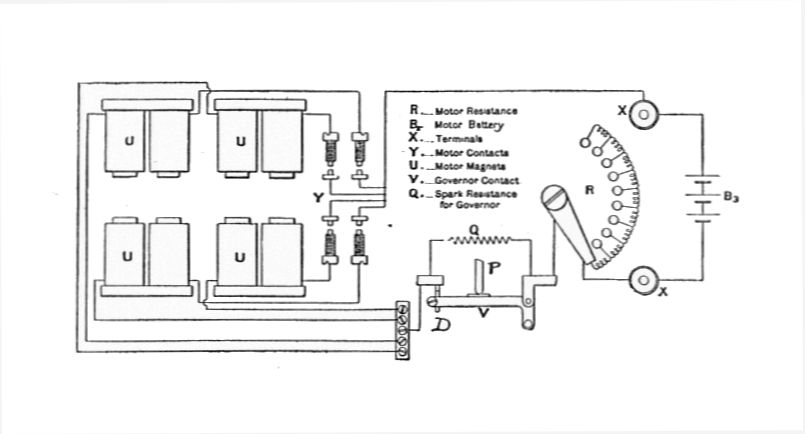
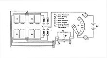 Circuit of a motor
The motor operates by simple magnetic attraction between one of the electromagnets and one of the iron bars. The bar is not permanently magnetized, nor does electrical current flow through any part of the rotor. Unlike the visually somewhat similar squirrel cage motor, no current flow is induced in the bars. The cams and switches are arranged so that as each bar approaches within range of the magnet the current is first switched on and the bar is pulled towards it. As it approaches closer, the current is then switched off and so the bar continues to rotate past the magnet, rather than being attracted to it and stopping there. Each of the coils, cams and switches is so arranged that each of the bars is attracted in turn and so the motor rotates continuously.[4]
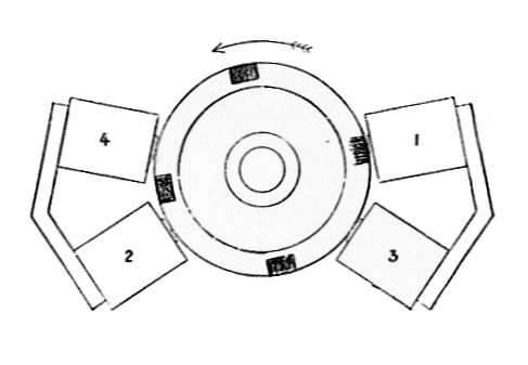
For balance, the bars are spaced symmetrically around the rotor. For a more even torque, the coils are spaced to be uneven, so that they each pull in turn, rather than all at once. In the diagram illustrated, the coil #1 has just switched off as a rotos bar passes it, #2 has switched on and is attracting the opposite bar towards it. This will be followed by #3 and #4 in turn.
If the motor has multiple electromagnets it is usually self-starting. The simpler single magnet form may require a flick to start it from some positions, continuing to rotate afterwards.
The motor always rotates in the same direction, as reversing it would require the phasing of the cams and switches to be changed. There is no record of motors being built for easy reversing, although it is not impossible.
There are the same number of switches as there are electromagnets, although many magnets were wound as horseshoes and so may appear to have two coils per magnet. Each switch is worked by as many cam pulses per revolution as there are attractor bars on the rotor. For small numbers of bars, the cam is formed with that many lobes. As there may commonly be six or eight bars on the rotor,[5] this makes the shaping of a workable cam awkward. It is then simpler to use a simple single-lobed cam, on a shaft geared up to be driven at four, six or eight times the rotor speed, according to the number of bars.
Governing
By using a simple centrifugal governor, the speed of the motor may be controlled. When the governor detects an over-speed it interrupts the cam linkage so that the switches are activated for less time and so the motor slows.[6] As there is already a cam and switch mechanism required, the addition of a governor link is a relatively simple addition. The use of a geared-up camshaft, as was common on the large power-producing motors, is also beneficial to permitting a smaller and more sensitive centrifugal governor. The ability to govern the power of the motor by switching the contact times gradually meant that this motor, unlike most other designs where the regulator shut off power altogether, meant that it could be governed very precisely.[6]
History
The motor was invented by the French electrical engineer Paul-Gustav Froment in 1844.[7] Froment's motor has some similarity to Ritchie's earlier motor of 1833.[8] The rotor of Ritchie's motor was the two ends of a single bar, rather than Froment's multiple bars, and so the torque was uneven with rotation. Several similar motors were known at this period, but they all suffered from drawbacks: depending on weakly magnetised materials rather than only requiring magnetic bars, requiring rotating coils and the as-yet unsolved problem of brushgear, or else reciprocating machines with additional cranks or ratchets and uneven rotation. Froment's motor was the first that offered a useful rotation and the capacity to do mechanical work, not merely to be a demonstration or indicator.
Telegraphy
Some decades after its first development, the motor was used in telegraphy to power the paper feed mechanism for both Kelvin's and Muirhead's syphon recorders.[9] These used a moving pen attached to a galvanometer to record telegraph signals. A paper roll was wound through the recorder by a Froment motor and the inked trace appeared as a wiggling line. Muirhead's design used a vibrating pen to avoid the ink causing the pen to stick against the tiny forces of the galvanometer. Kelvin's design instead used a hollow glass pen with an electrostatic charge to propel ink from the syphon tube.[10] This charge was generated by an influence machine, also driven by the motor.
Similar, although larger, machines were later developed to record Morse code telegraphy.
The mechanically-governed mouse mill motor, as described here, could maintain a reasonably accurate speed but was not a synchronous motor. Where a telegraph machine depending on precise timing to signal letters, a synchronous motor such as that developed by Paul Le Cour was used.
References
- ^ Greenslade, Prof. Thomas B. Jr.. "Revolving Armature Engine". http://physics.kenyon.edu/EarlyApparatus/Daniel_Davis_Apparatus/Revolving_Armature_Engine/Revolving_Armature_Engine.html.
- ^ Greenslade, Prof. Thomas B. Jr.. "Froment Motors". http://physics.kenyon.edu/EarlyApparatus/Electric_Motors/Froment_Motor/Froment_Motor.html.
- ^ Greenslade, Prof. Thomas B. Jr.. "Daniel Davis". http://physics.kenyon.edu/EarlyApparatus/Daniel_Davis_Apparatus/Daniel_Davis,_Jr._Portrait/Davis_Portrait.html.
- ^ Kennedy, Rankin (1903). Telegraph Motors. Electrical Installations (1903 five-volume ed.). London: Caxton. pp. 76–79.
- ^ "Froment's "mouse-mill" motor (8 attractors, one electromagnet)". http://www.scran.ac.uk/database/record.php?usi=000-000-529-517-C.
- ^ a b Kennedy, Electrical Installations, 1903, p. 77
- ^ "Early History of the Electric Motor". The Old Model Company. http://www.oldmodels.co.uk/history.htm.
- ^ "The Development of the Electric Motor". http://www.sparkmuseum.com/MOTORS.HTM.
- ^ Kennedy, Electrical Installations, 1903, p. 78
- ^ Kennedy, Electrical Installations, 1903, p. 79
Categories:- Early electric motors
- Electric motors

Wikimedia Foundation. 2010.