- Dynamic insulation
-
Dynamic insulation is a form of insulation where cool outside air flowing through the thermal insulation in the envelope of a building will pick up heat from the insulation fibres. Buildings can be designed to exploit this to reduce the transmission heat loss (U-value) and to provide pre-warmed, draft free air to interior spaces. This is known as dynamic insulation since the U-value is no longer constant for a given wall or roof construction but varies with the speed of the air flowing through the insulation. Dynamic insulation is different from breathing walls. The positive aspects of dynamic insulation need to be weighed against the more conventional approach to building design which is to create an airtight envelope and provide appropriate ventilation using either natural ventilation or mechanical ventilation with heat recovery. The air-tight approach to building envelope design, unlike dynamic insulation, results in a building envelope that provides a consistent performance in terms of heat loss and risk of interstitial condensation that is independent of wind speed and direction. Under certain wind conditions a dynamically insulated building can have a higher heat transmission loss than an air-tight building with the same thickness of insulation.
Contents
Introduction
The primary function of the walls and roof of a building is to be wind and watertight. Depending on the function of the building there will be also a requirement to maintain the inside within a suitable temperature range in a way that minimises both the use of energy and the associated carbon dioxide emissions.
 Conventionally insulated airtight wall
 Dynamic insulation wallFig 1 Airtight and air permeable walls compared
Dynamic insulation is normally implemented in timber frame walls and in ceilings. It turns on its head the long accepted wisdom of building designers and building services engineers to “build tight and ventilate right”[1]. It requires air permeable walls and/or roof/ceiling so that when the building is depressurised air can flow from outside to inside through the insulation in the wall or roof or ceiling (Figs 1 and 2). The following explanation of dynamic insulation will, for simplicity, be set in the context of temperate or cold climates where the main energy use is for heating rather than cooling the building. In hot climates it may have application in increasing the heat loss from the building.
As air flows inwards through the insulation it picks up, via the insulation fibres, the heat that is being conducted to the outside. Dynamic insulation is thus able to achieve the dual function of reducing the heat loss through the walls and/or roof whilst at the same time supplying pre-warmed air to the indoor spaces. Dynamic insulation would appear, therefore, to overcome the major disadvantage of airtight envelopes which is that the quality of the indoor air will deteriorate unless there is natural or mechanical ventilation. However, dynamic insulation also requires mechanical ventilation with heat recovery (MVHR) in order to recover the heat in the exhaust air.
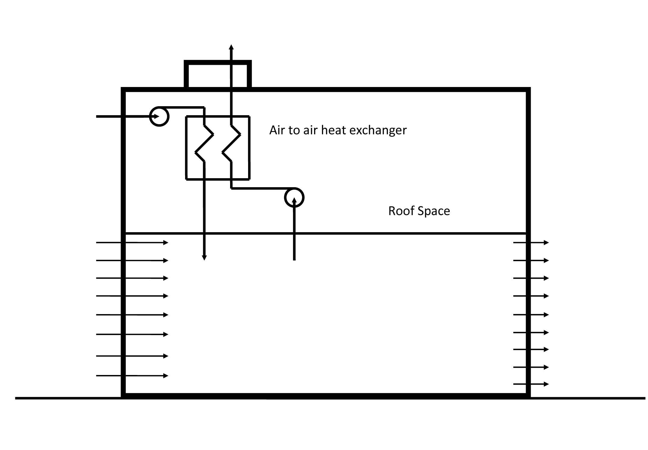
For the air to be continually drawn through the walls and/or roof/ceiling, a fan is needed to hold the building at a pressure of 5 to 10 Pascals below the ambient pressure. The air that is being continuously drawn through the wall or roof needs to be continuously vented to outside. This represents a heat loss which must be recovered. An air to air heat exchanger (Fig 2) is the simplest way to do this.
Annotation for Air Tight Timber Frame ConstructionElement Description 1 brick cladding 2 ventilated cavity 3 sheathing board with breathing membrane on exterior surface 4 insulation 5 plasterboard (vapour control layer optional)  Fig 2 Dynamically insulated house viewed as a system
Annotation for Air Permeable Wall ConstructionElement Description 1 brick cladding 2 ventilated cavity 3 sheathing board (air permeable) 4 insulation (air permeable) 5 air control layer 6 ventilated cavity 7 plasterboard Science of dynamic insulation
All the main features of dynamic insulation can be understood by considering the ideal case of one-dimensional steady state heat conduction and air flow through a uniform sample of air permeable insulation. Equation (1), which determines the temperature T at a distance x measured from the cold side of the insulation, is derived from the total net flow of conduction and convective heat across a small element of insulation being constant.
-

(
where
u air speed through the insulation (m/s)
ca specific heat of air (J/kg K)
ρa density of air (kg/m3)
λa thermal conductivity of the insulation(W/m K)
For two and three dimensional geometries computational fluid dynamics (CFD) tools are required to solve simultaneously the fluid flow and heat transfer equations through porous media. The idealised 1D model of dynamic insulation provide a great deal of physical insight into the conductive and convective heat transfer processes which provides a means of testing the validity of the results of CFD calculations. Furthermore, just as simple 1D steady state heat flow is assumed in the calculation of the heat transmission coefficients (U-values) that are used in the design, approval and building energy performance rating of buildings so the simple 1D steady state model of dynamic insulation is adequate for designing and assessing the performance of a dynamically insulated building or element of the building.
Insulations such as polyurethane (PUR) boards, which due to their micro-structure, are not air permeable are not suitable for dynamic insulation. Insulations such as rock wool, glass wool, sheeps' wool, cellulose are all air permeable and so can be used in a dynamically insulated envelope. In equation (1) the air speed through the insulation, u is taken as positive when the air flow is in the opposite direction to the conductive heat flow (contra-flux). Equation (1) also applies to steady state heat flow in multi-layred walls [2].Equation (1) has an analytical solution [3]
-

(
For the boundary conditions:T(x) = To at x = 0
T(x) = TL at x = L
where the parameter A, with dimensions of length, is defined by:
-

(
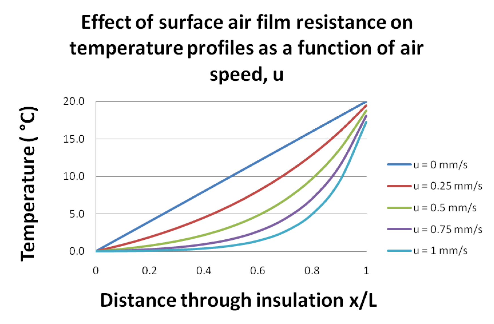
The temperature profile as calculated using equation (2) for air flowing through a slab of cellulose insulation 0.2 m thick in which one side is at a temperature of 20 °C and the other is at 0 °C is shown in Fig 3. The thermal conductivity of cellulose insulation was taken to be 0.04 W/m2K [4]. Fig 3 Air flowing through insulation from cold side to warm side (contra flux)
Contra-flux
Fig 3 shows the typical behaviour of the temperature profile through dynamic insulation where the air flows in the opposite direction to the heat flux. As the air flow increases from zero, the temperature profile becomes increasingly more curved. On the cold side of the insulation (x/L = 0) the temperature gradient becomes increasingly horizontal. As the conduction heat flow is proportional to the temperature gradient, the slope of the temperature profile on the cold side is a direct indication of the conduction heat loss through a wall or roof. On the cold side of the insulation the temperature gradient is close zero which is the basis for the claim often made that dynamic insulation can achieve a U-value of zero W/m2K.
On the warm side of the insulation the temperature gradient gets steeper with increasing air flow. This implies heat is flowing into the wall at a greater rate than for conventional insulation (air speed = 0 mm/s). For the case shown of air flowing through the insulation at 1mm/s the temperature gradient on the warm side of the insulation x/L = 1) is 621 °C/m which compares with only 100 °C/m for the conventional insulation. This implies that with an air flow of 1mm/s the inner surface is absorbing 6 times as much heat as that for conventional insulation.
A consequence of this is that considerably more heat has to be put into the wall if there is air flowing through from outside. Specifically a space heating system six time larger than that for a conventionally insulated house would be needed. It is frequently stated that in dynamic insulation the outside air is being warmed up by heat that would be lost in any case[5]. The implication being that the outside air is being warmed by "free" heat. The fact that the heat flow into the wall increases with air speed is evidenced by the decreasing temperature of the inner surface (Table 2 and Fig 4 below). A dynamically insulated house requires also an air-to-air heat exchanger as does an airtight house. The latter has the further advantage that if it is well insulated it will require only a minimal space heating system.
The temperature gradient at point in dynamic insulation can be obtained by differentiating equation (2)-

(
From this the temperature gradient on the cold side of the insulation (x = 0) is given by-

(
and the temperature gradient on the warm side of the insulation (x = L) is given by
-

(
From the temperature gradient on the cold side of the insulation (equation (5)) a transmission heat loss or U-value for a dynamically insulated wall, Udyn can be calculated (Table 1)
-

(
This definition of dynamic U-value would appear to be consistent with Wallenten's definition[3].
The ratio of the dynamic U-value to the static U-value (u=0 m/s) is
-

(
Table 1 Dynamic U-valueAir speed u, (mm/s) Temp gradient at x/L=0 (°C/m) Conductive heat loss (W/m2) Udyn (W/m2 K) 0 100 4 0.2 0.25 41.8 1.672 0.084 0.5 14.6 0.584 0.029 0.75 4.49 0.1796 0.009 1.0 1.26 0.0504 0.003
With this definition, the U-value of the dynamic wall decreases exponentially with increasing air speed.As stated above the conductive heat flow into the insulation on the warm side is very much greater than that leaving the cold side. In this case it is 6.21 X 4 / 0.0504 = 493 times for an air speed of 1 mm/s (Table 1). This imbalance in conductive heat flow is raising the temperature of the incoming air.
This large heat flow into the wall has a further consequence. At the surface of a wall, floor or ceiling there is thermal resistance which takes account of the convective and radiant heat transfer at these surfaces. For a vertical internal surface this thermal resistance has a value of 0.13 m2 K/W [6]. In a dynamically insulated wall, as the conduction heat flow into the wall increases then so does the temperature drop across this internal thermal resistance increase. The wall surface temperature will become increasingly colder (Table 2). The temperature profiles through dynamic insulation taking into account the decrease in surface temperature with increasing air flow is shown in Fig 4.
 Fig 4 Air flowing through insulation from cold side to warm side (contra flux)
Table 2 Temperature drop across air film thermal resistance
Air speed u,(mm/s) Temperature drop across the air film (°C) 0 0.52 0.25 1.02 0.5 1.69 0.75 2.44 1.0 3.23
As the operative temperature of a room is a combination of the air temperature and the mean temperature of all the surfaces in the room this implies that people will feel increasingly cooler as the air flow through the wall increases. Occupants may be tempted to turn up the room thermostat to compensate and thereby increasing the heat loss.Pro-flux
 Fig 5 Air flowing through insulation from warm side to cold side (pro-flux)
 Fig 6 Heat Transmission through Wall v Air Speed through the Insulation
Fig 5 shows the typical behaviour of the dynamic insulation temperature profile when the air flows in the same direction to the conductive heat flow (pro-flux). As air at room temperature flows outwards with increasing speed the temperature profile becomes increasingly more curved. On the warm side of the insulation the temperature gradient becomes increasingly horizontal as the warm air prevents the insulation cooling down in the linear way that would occur with no air flow. The conductive heat loss into the wall is very much less than that for conventional insulation. This does not mean that the transmission heat loss for the insulation is very low.
On the cold side of the insulation the temperature gradient gets steeper with increasing air outward flow. This is because the air, having now cooled, is no longer able to transfer heat to the insulation fibres. In pro-flux mode heat is flowing out of the wall at a greater rate than the case for conventional insulation. Warm moist air flowing out through the insulation and cooling rapidly increases the risk of condensation occurring within the insulation which will degrade the thermal performance of the wall and could, if prolonged, lead to mould growth and timber decay.
How the heat flow (W/m2K) from the outer or cold surface of the insulation varies with air flow through the insulation is shown in Fig 6. When the air, which is also cold, flows inwards (air speed is positive) then the heat loss decreases from that of conventional insulation towards zero. However, when warm air flows outwards through the insulation (air speed is negative) then the heat losses increase dramatically. This is why in a conventionally insulated building it is desirable to make the envlope airtight. In a dynamically insulated wall it is necessary to ensure the air flow is inward at all points of the building under all wind speeds and directions.
Influence of the wind
In general when the wind blows on a building then the air pressure, Pw varies all over the building surface (Fig 7) [7].
 Fig 7 Wind Pressure Distribution around a Building (Liddament, 1986)
-

(
wherePo a reference pressure (Pa)
Cp wind pressure coefficient (dimensionless)
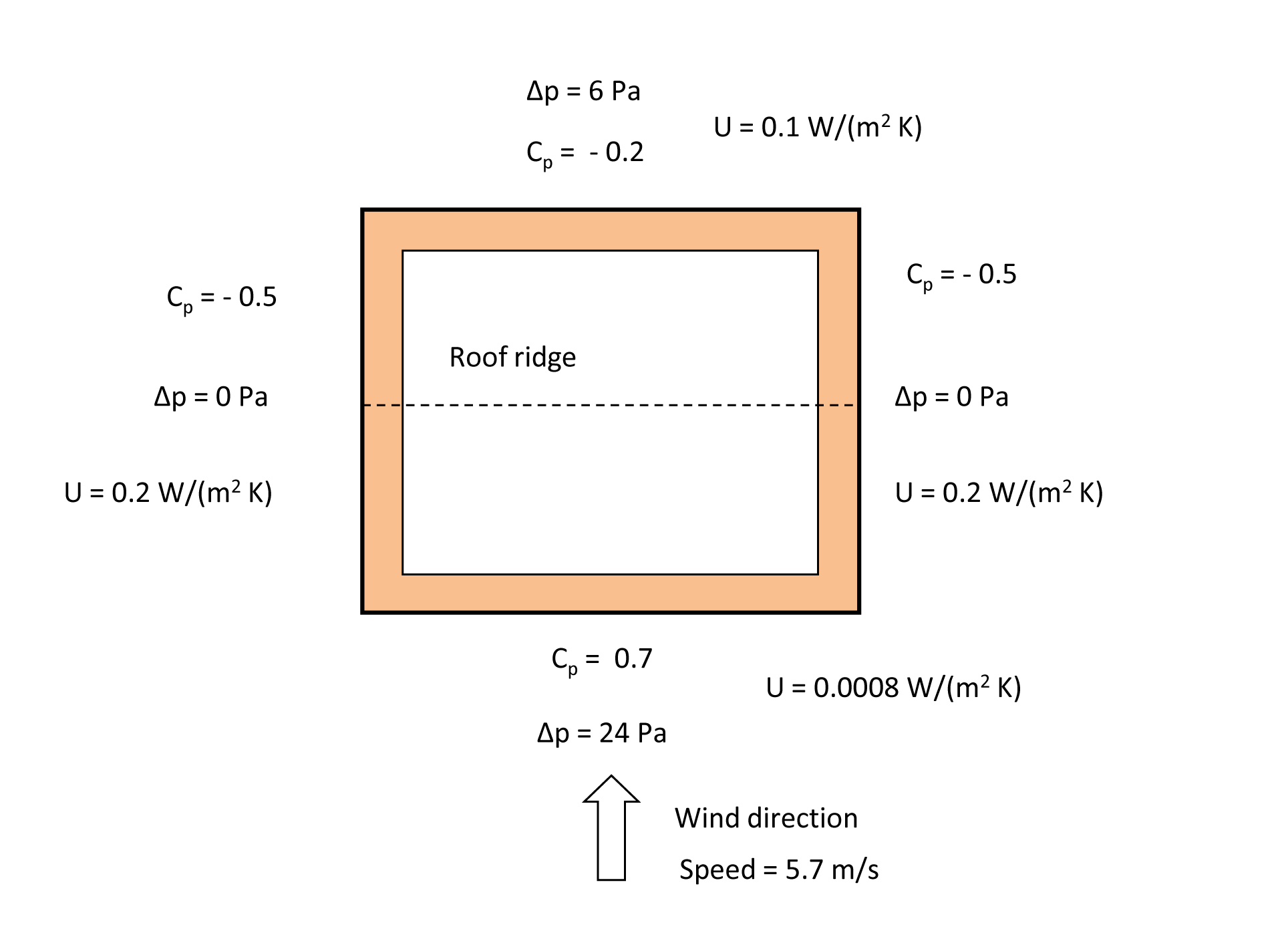
Liddament[7], and CIBSE[6], provide approximate wind pressure coefficient data for low rise buildings (up to 3 storeys). For a square plan building on an exposed site with the wind blowing directly on to the face of the building the wind pressure coefficients are as shown in Fig 8. For a wind speed of 5.7 m/s at ridge height (taken as 8m) there is zero pressure difference across the side walls when the building is depressurised to -10 Pa. The insulation in the windward and leeward walls is behaving dynamically in the contra-flux mode with U-values of 0.0008 W/(m2K) and 0.1 W/(m2K) respectively. Since the building has a square footprint the average U-value for the walls is 0.1252 W/m2K. For other wind speeds and directions, the U-values will be different.
For wind speeds greater than 5.7 m/s at ridge height then the side walls are in pro-flux mode with a U value dramatically increasing with wind speed (Fig 6) At wind speeds greater than 9.0 m/s at ridge height the lee-ward switches from contra-flux to pro-flux mode. The average U-value for the four walls is now 0.36 W/(m2K), which is significantly greater than the 0.2 W/(m2K) for an air-tight construction. These changes from contra-flux to pro-flux mode could be delayed by depressurising the building below -10 Pa.By locating this building in a particular geographical location then wind speed data for this site may be used to estimate the proportion of the year in which one or more of the walls will be operating in the risky and high heat loss pro-flux mode. From the Rayleigh distribution of wind speed at the site of the building, it is possible to estimate the number of hours in a year during which the wind speed at a height of 10.0 m exceeds 7.83 m/s (estimated from the wind speed of 5.7 m/s at ridge height of 8.0 m) [7]. This is the total time during an average year in which a building with dynamically insulated walls has significant heat losses.
If, by way of example, the building in Fig 8 were located in Footdee, Aberdeen, the Ordnance Survey Land Ranger grid reference is NJ955065. Entering NJ9506 into the UK windspeed data base [8] returns for this site an average annual wind speed of 5.8 m/s at a height of 10 m. The Rayleigh distribution for this mean wind speed indicates wind speeds in excess of 8 m/s are likely to occur for 2348 hours in the year or about 27% of the year. The wind pressure coefficients for the walls of the building vary also with wind direction which changes throughout the year. Nevertheless the above calculations indicate that a square plan building of 2 storeys located in Footdee, Aberdeen could have one or more of the walls operating in the risky and high heat loss pro-flux mode for about a quarter of the year.
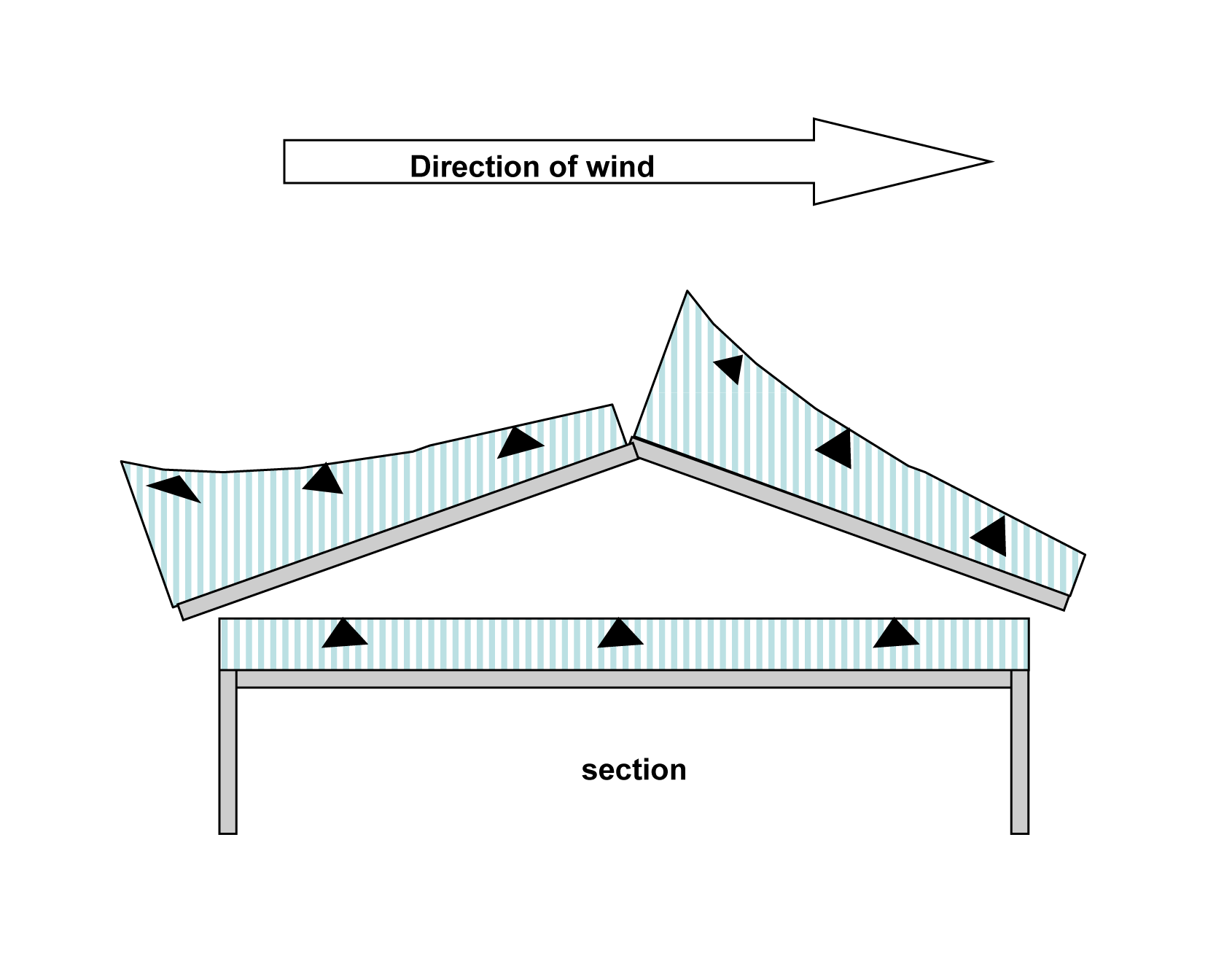
A more robust way of introducing dynamic insulation to a building that avoids the pressure variation around the building envelope is to make use of the fact that in a ventilated roof space the pressure is relatively uniform over the ceiling (Fig 9 ) [7]. Thus a building with a dynamically insulated ceiling would offer a consistent performance independent of a varying wind speed and direction.
 Fig 8 Wind Pressure Coefficients for Low Rise Building on a Exposed Site(Liddament, 1986)
 Fig 9 Wind Pressure Distribution around Ventilated Roof.png(Liddament, 1986)
Air control layer
The maximum depressurisation for a dynamically insulated building is normally limited to 10 Pa in order to avoid doors slamming shut or difficulty in opening doors[9]. Dalehaug also recommended that the pressure difference through the construction at the design minimum air flow (> 0.5 m3/m2h) should be about 5 Pa. The function of the air control layer (Fig 1) in a dynamically insulated wall or ceiling is provide sufficient resistance to the air flow to achieve the required pressure drop at the design air flow rate. The air control layer requires to have a suitable air permeability and this is the key to making dynamic insulation work.
The permeability of a material to air flow, Φ, (m2/hPa) is defined as the volume of air that flows through a cube of material 1m X 1m X 1m in one hour
-

(
whereA area of material through which air flows (m2)
L thickness of material through which air flows (m)
V' volume flow rate of air (m3/h)
ΔP pressure difference along the length L of material (Pa)
Equation (10) is a simplified form of Darcy's Law. In building applications the air is at ambiant pressure and temperature and small changes in the viscosity of air are not significant. Darcy's Law can be used to calculate the air permeability of a porous medium if the permeability of the medium (m2) is known.
The air permeability of some materials that could be used in dynamically insulated walls or ceiling are listed in Table 3. Air permeability data is crucial to the selection of the correct material for the air control layer. Further sources of air permeability data include ASHRAE[10] and Kumaran[11].
Table 3: Measured Air Permeability of Building Materials [12]Material Density (kg/m3) Permeability (m2/hPa) Component Permeance(m3/m2hPa) Pressure Drop1 (Pa) Plasterboard - 1.06x10⁻⁵ 12 mm sheet 8.81x10⁻⁴ 1140 Thermal block 850 1.6x10⁻⁵ 100 mm block 1.6x10⁻⁴ 526 Fibreboard - 1.34x10⁻³ 12 mm sheet 0.116 8.6 “Pumalite” 870 0.036 100 mm block 0.36 2.8 Cellulose / wet blown 47 0.283 200 mm 1.50 0.67 Cellulose / dry blown 65 0.25 150 mm 1.67 0.60 Sheep's wool 28 1.8 140 mm 13.0 0.08 (1) Pressure drop calculated at flow rate of 1 m3/m2h
Design of a dynamic insulated building
The application of the theory of dynamic insulation is best explained by way of an example. Assume a house of 100 m2 floor area with a dynamically insulated ceiling. Putting dynamic insulation in the ceiling effectively limits the house to a single storey.
The first step is to decide on an appropriate air change rate for good air quality. As this air flow rate will be supplied through the dynamically insulated ceiling and a mechanical ventilation and heat recovery system (MVHR), energy loss is not a major concern so 1 air change per hour (ach) will be assumed. If the floor to ceiling height is 2.4 m this implies an air flow rate of 240 m3/h, part of which is supplied through the dynamically insulated ceiling and partly through the MVHR.
Next the material for the air control layer is chosen to provide a suitable air flow rate at the chosen depressurisation, taken as 10 Pa in this case. (The air flow rate could be determined from the desired U-value at the depressurisation of 10 Pa.) From Table 4, fibreboard has an appropriate air permeability of 1.34x10⁻³ (m2/hPa).
For a 12mm thick sheet of fibreboard this gives, for the maximum pressure difference of 10 Pa, an air flow rate of 1.12 m3/h per m2 of ceiling. This is equivalent to an air speed through the ceiling of 1.12 m/h or 0.31 mm/s. The 100 m2 ceiling will thus provide 112 m3/h and therefore an air to air heat exchanger will provide the balance of 128 m3/h
Dynamic insulation works best with a good thickness of insulation so taking 200 mm of cellulose insulation (k = 0.04 W/m °C) the dynamic U value for an air flow of 0.31 mm/s is calculated using equation (7) above to be 0.066 W/m2 °C. If a lower dynamic U-value is required then a material with lower air permeability than fibreboard would need to be selected for the air control layer, so that a higher air speed through the insulation at 10 Pa can be achieved.
The final step would be to select an air to air heat exchanger that had a good heat recovery efficiency with a supply air flow rate of 128 m3/h and an extract air flow rate of 240 m3/h.
See also
- List_of_insulation_material
- Wind loads on buildings
- Laminar_flow
- Porous_medium
References
- ^ Easley, S., 2007, How Tight is too Tight?, LBM Journal, Nov. www.LBMJournal.com
- ^ Taylor, B. J., Cawthorne, D. A., Imbabi, M. S., 1996, Analytical Investigation of the Steady-State Behaviour of Dynamic and Diffusive Envelopes, Building and Environment, 31, pp 519-525
- ^ a b Wallenten, P., 1995, Analytical and Numerical Analysis of Dynamic Insulation, International, Building Performance Simulation Association, Fourth International Conference, 14 – 16 August, Madison, Wisconsin
- ^ Pfunstein, M., Gellert, R., Spitzner, M H., Rudolphi, A., 2007, DETAIL Practice, Insulating Materials, Birkhauser, Basel
- ^ Hines, J., 1999, The Architects' Journal, 4 February 1999
- ^ a b CIBSE, 2006, CIBSE Guide A, Environmental Design, 7th ed., CIBSE, London
- ^ a b c d Liddament, M. W., 1986, Air Infiltration Calculation Techniques – An Applications Guide, Air Infiltration and Ventilation Centre, Bracknell
- ^ Department of Energy and Climate Change (DECC), 2001, UK Wind Speed Database, http://www.decc.gov.uk/en/content/cms/what_we_do/uk_supply/energy_mix/renewable/explained/wind/windsp_databas/windsp_databas.aspx
- ^ Dalehaug, A., 1993, Dynamic Insulation in Walls, Research Report No. 53, Hokkaido Prefectural Cold Region Housing and Urban Research Institute
- ^ ASHRAE, 2009, ASHRAE Handbook, Fundamentals, Chapter 26, Table 8, Atlanta
- ^ Kumaran, M K., 1996, Heat, Air and Moisture Transfer in Insulated Envelope Parts, final Report, vol 3, Task 3: Material Properties, International Energy Agency Annex 24
- ^ Taylor, B J., and Imbabi, M. S, 2000, Environmental Design using Dynamic Insulation, ASHRAE Transactions, 106, Part 1
External links
“OpenAir@RGU” Further resources on the theory and applications of dynamic insulation can be found at the open access institutional repository of Robert Gordon University.
Categories:- Insulators
-


Wikimedia Foundation. 2010.