- Crankcase ventilation system
-

A crankcase ventilation system is a way for gases to escape in a controlled manner from the crankcase of an internal combustion engine. A common type of such system is a positive crankcase ventilation (PCV) system, the heart of which is a PCV valve—a variable-restriction valve that can react to changing pressure values and intermittently allow the passage of the gases to their intended destination (which nowadays is the engine's intake stream).
Internal combustion inevitably involves a small but continual amount of blow-by, which occurs when some of the gases from the combustion leak past the piston rings (that is, blow by them) to end up inside the crankcase. The gases could be vented through a simple hole or tube directly to the atmosphere, or they could "find their own way out" past baffles or past the oil seals of shafts or the gaskets of bolted joints. This is not a problem from a mechanical engineering viewpoint alone; but from other viewpoints, such as cleanliness for the user and environmental protection, such simple ventilation methods are not enough; escape of oil and gases must be prevented via a closed system that routes the escaping gases to the engine's intake stream and allows fresh air to come in.
Contents
History of gradual development
From the late 19th century through the early 20th, blow-by gases were allowed to find their own way out past seals and gaskets. It was considered normal for oil to be found both inside and outside an engine, and for oil to drip to the ground in small but constant amounts. This had also been true for steam engines and steam locomotives in the decades before. Even bearing and valve designs generally made little to no provision for keeping oil or waste gases contained. Sealed bearings and valve covers were for special applications only. For example, oilers kept the locomotives and rolling stock of railroads continually supplied with oil both inside and out. Although it was applied sparingly to oil cups and oil holes, it was not expected to stay hermetically sealed off from dripping and leaking to the wider environment. Gaskets and shaft seals were meant to limit loss of oil, but they were usually not expected to entirely prevent it. On internal combustion engines, the hydrocarbon-rich blow-by gases would diffuse through the oil in the seals and gaskets into the atmosphere. Engines with high amounts of blow-by (e.g., worn out ones, or ones not well built to begin with) would leak profusely via those routes.
From 1928 until the early 1960s, car and truck petrol engines vented combustion gases directly to the atmosphere through a simple vent tube. Frequently, this consisted of a pipe (the 'road draft tube') that extended out from the crankcase down to the bottom of the engine compartment. The bottom of the pipe was open to the atmosphere, and was placed such that when the car was in motion a slight vacuum was obtained, helping to extract combustion gases as they collected in the crankcase. The vacuum was satisfied by a vent, typically in the valve or valley cover, creating a constant flow of clean air through the engine's air volume. The oil mist would also be discharged, resulting in an oily film being deposited in the middle of each travel lane on heavily-used roads. The system was not positive though, as gases could travel both ways, or not move at all, depending on conditions. (Most modern diesel engines still use this type of system to dispose of crankcase fumes.)
During World War II, however, a different type of crankcase ventilation had to be invented to allow tank engines to operate during deep fording operations, where the normal draft tube ventilator would have allowed water to enter the crankcase and destroy the engine. The PCV system and its control valve were invented to meet this need, but no need for it on automobiles was recognized.
In 1952, Professor A. J. Haagen-Smit, of the California Institute of Technology at Pasadena, postulated that unburned hydrocarbons were a primary constituent of smog, and that gasoline powered automobiles were a major source of those hydrocarbons. After some investigation by the GM Research Laboratory (led by Dr. Lloyd L. Withrow), it was discovered in 1958 that the road draft tube was a major source, about half, of the hydrocarbons coming from the automobile. GM's Cadillac Division, which had built many tanks during WWII, recognized that the simple PCV valve could be used to become the first major reduction in automotive hydrocarbon emissions. After confirming the PCV valves' effectiveness at hydrocarbon reduction, GM offered the PCV solution to the entire U.S. automobile industry, royalty free, through its trade association, the Automobile Manufacturers Association (AMA). In the absence of any legislated requirement, the AMA members agreed to put it on all California cars voluntarily in 1961, with national application following one year later, in 1962.
In 1967, several years after its introduction into production, the PCV system became the subject of a U.S. federal grand jury investigation, when it was alleged by some industry critics that the AMA was conspiring to keep several such smog reduction devices on the shelf to delay further smog control. After eighteen months of investigation by U.S. Attorney Samuel Flatow, the grand jury returned a "no-bill" decision, clearing the AMA, but resulting in a "Consent Decree" that all U.S. automobile companies agreed not to work jointly on smog control activities for a period of ten years.
In the decades since, the legislation and regulation around emissions has tightened substantially, and the emissions of cars and light trucks have decreased substantially. Today's petrol engines continue to use PCV systems in addition to many other emissions control measures, many of which reduce toxic exhaust emissions by relying on sensors (to collect status information for computer input), engine control units (for information processing), and actuators (to translate computer output to the changing of conditions).
System components and operation details
 PCV valve on Ford Taunus V4 engine in a Saab 96, between left valve cover and intermediate flange on intake manifold
The PCV valve is only one part of the PCV system, which is essentially a variable and calibrated air leak, whereby the engine returns its crankcase combustion gases. Instead of the gases being vented to the atmosphere, gases are fed back into the intake manifold, to re-enter the combustion chamber as part of a fresh charge of air and fuel. The PCV system is not a classical "vacuum leak". All the air collected by the air cleaner (and metered by the mass flow sensor, on a fuel injected engine) goes through the intake manifold. The PCV system just diverts a small percentage of this air via the breather to the crankcase before allowing it to be drawn back in to the intake tract again. It is an "open system" in that fresh exterior air is continuously used to flush contaminants from the crankcase and into the combustion chamber.
The system relies on the fact that, while the engine is running under light load and moderate throttle opening, the intake manifold's air pressure is always less than crankcase air pressure. The lower pressure of the intake manifold draws air towards it, pulling air from the breather through the crankcase (where it dilutes and mixes with combustion gases), through the PCV valve, and into the intake manifold.
The PCV system usually consists of the breather tube and the PCV valve. The breather tube connects the crankcase to a clean source of fresh air—the air cleaner body. Usually, clean air from the air cleaner flows into this tube and into the engine after passing through a screen, baffle, or other simple system to arrest a flame front, to prevent a potentially explosive atmosphere within the engine crank case from being ignited from a back-fire in to the intake manifold. The baffle, filter, or screen also traps oil mist, and keeps it inside the engine.
Once inside the engine, the air circulates around the interior of the engine, picking up and clearing away combustion byproduct gases, including a large amount of water vapor which includes dissolved chemical combustion byproducts, then exits through another simple baffle, screen, or mesh to trap oil droplets before being drawn out through the PCV valve, and into the intake manifold. On some PCV systems, this oil baffling takes place in a discrete replaceable part called the oil separator.
During the mid 1960s, substantial work was completed on an entirely independent crankcase ventilation system. The Engine Ventilation System had its own air intake filter, a sizable crankcase gases filter, condensate chamber, and highly engineered air flow valve.[citation needed] The system recycles clean water vapor, filters light oil, and filters air into the intake system before the carburetor, resulting in lower carbon monoxide and hydrocarbon emissions and extended engine oil life. Ford Motor Company made this system a requirement on all its material handling equipment (lift trucks) in 1971. This system was also used extensively on over-the-road diesel trucks and irrigation pumps. The AMA's choice[clarification needed] of catalytic converter made automotive use unlikely.[citation needed]
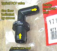
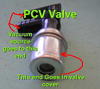
The PCV valve connects the crankcase to the intake manifold from a location more-or-less opposite the breather connection. Typical locations include the opposite valve cover that the breather tube connects to on a V engine. A typical location is the valve cover(s), although some engines place the valve in locations far from the valve cover. The valve is simple, but actually performs a complicated control function. An internal restrictor (generally a cone or ball) is held in "normal" (engine off, zero vacuum) position with a light spring, exposing the full size of the PCV opening to the intake manifold. With the engine running, the tapered end of the cone is drawn towards the opening in the PCV valve by manifold vacuum, restricting the opening proportionate to the level of engine vacuum vs. spring tension. At idle, the intake manifold vacuum is near maximum. It is at this time the least amount of blow by is actually occurring, so the PCV valve provides the largest amount of (but not complete) restriction. As engine load increases, vacuum on the valve decreases proportionally and blow by increases proportionally. With a lower level of vacuum, the spring returns the cone to the "open" position to allow more air flow. At full throttle, vacuum is much reduced, down to between 1.5 and 3" Hg. At this point the PCV valve is nearly useless, and most combustion gases escape via the "breather tube" where they are then drawn in to the engine's intake manifold anyway.
Should the intake manifold's pressure be higher than that of the crankcase (which can happen in a turbocharged engine, or under certain conditions, such as an intake backfire), the PCV valve closes to prevent reversal of the exhausted air back into the crankcase again. In many cases PCV valves were only used for a few years, the function being taken over by a port on constant depression carburetors such as the SU. This has no moving parts or diaphragm to jam, block or rip like many PCV valves. It also doesn't have a 'one-way' function but the lack of it was never a problem in intake backfire.
It is critical that the parts of the PCV system be kept clean and open, otherwise air flow will be insufficient. A plugged or malfunctioning PCV system will eventually damage an engine. PCV problems are primarily due to neglect or poor maintenance, typically engine oil change intervals that are inadequate for the engine's driving conditions. A poorly-maintained engine's PCV system will eventually become contaminated with sludge, causing serious problems. If the engine's lubricating oil is changed with adequate frequency, the PCV system will remain clear practically for the life of the engine. However, since the valve is operating continuously as one operates the vehicle, it will fail over time. Typical maintenance schedules for gasoline engines include PCV valve replacement whenever the air filter or spark plugs are replaced. The long life of the valve despite the harsh operating environment is due to the trace amount of oil droplets suspended in the air that flows through the valve that keep it lubricated.
Alternatives in non-car-and-light-truck usage
Not all petrol engines have PCV valves. Engines not subject to emission controls, such as certain off-road engines, retain road draft tubes. Dragsters use a scavenger system and venturi tube in the exhaust to draw out combustion gases and maintain a small amount of vacuum in the crankcase to prevent oil leaks on to the race track. Small gasoline two stroke engines use the crankcase to partially compress incoming air. All blow by in these engines is burned in the regular flow of air and fuel through the engine. Many small four-cycle engines such as lawn mower engines and small gasoline generators, simply use a draft tube connected to the intake, between the air filter and carburetor, to route all blow by back into the intake mixture. The higher operating temperature of these small engines has a side effect of preventing large amounts of water vapor and light hydrocarbons from condensing in the engine oil.
References
Categories:- Engine valves
- Engine technology
- Pollution control technologies


Wikimedia Foundation. 2010.