- Course Setting Bomb Sight
-
 The CSBS Mk. IX mounted in a Fairey Battle. The bomb aimer is sighting through the white ring-shaped backsights to the pin shaped foresights (just visible against the armoured cable) and holding the bomb release switch in his right hand.
The Course Setting Bomb Sight (CSBS) is the canonical "vector" bombsight, the first practical system for properly accounting for the effects of wind during the dropping of bombs. It is also widely referred to as the Wimperis sight after its inventor, Harry Wimperis, who introduced it in 1917.
The CSBS was originally developed for the Royal Naval Air Service (RNAS) in order to attack submarines and ships. It was such a great advance over earlier designs that it was quickly adopted by the Royal Flying Corps, and the Independent Air Force. It has been called "the most important bomb sight of the war".[1][2]
After the war the design found widespread use around the world, and was used well into World War II. It was eventually replaced in British service by the more advanced designs like the Mark XIV bomb sight and the Stabilized Automatic Bomb Sight. Other services used vector bombsights throughout the war.
Contents
History
Early bombsights
Prior to the introduction of the CSBS, bombsights were generally very simple systems of limited accuracy suitable only for low-level use. The primary pre-war device in RNAS service was the Lever Sight, which the pilot had to hold out of the cockpit in one hand while flying the aircraft with the other. The Central Flying School Sight replaced this in 1915, but was difficult to install in the cockpit. The CFS was in turn replaced by the Equal Distance Sight designed in 1916 by Warrant Officer Scarff, better known for the development of the Scarff ring. The EDS allowed the bomb-run parameters to be entered once and then left the pilot free to fly the plane.[3]
None of these sights had a way to calculate "drift", the sideways motion of the bombs due to wind. This meant the aircraft had to attack their targets directly along the wind line.[1] Even in this direction, the wind would cause the bombs to fall long or short. To correct for this, the bomb aimer would first measure their speed over the ground using a stopwatch. They would next look up the time it would take the bombs to reach the ground from their current altitude using a pre-computed table, and using both values look up the proper angle for the sights, the so-called "range angle".[4] This solution was far from practical, and prone to error.
In 1916, Henry Wimperis started design of a new bombsight, working in collaboration with Scarff.[1] His Drift Sight included a simple system for calculating the effects of wind. Before the bomb run, the aircraft would first fly at right angles to the bomb line. By observing the sideways drift of the aircraft compared to a rod on the bombsight, the rod could be rotated until the drift was zeroed out. This directly measured the wind's effect on the groundspeed of the aircraft. This value was also the amount the bombs would fall long or short, and simply moving the rod moved the sights to account for this effect. This eliminated the need for a stopwatch to measure the ground speed, although it was still useful only for bomb runs along the wind line.[4]
Course Setting Bomb Sight
When an aircraft flies in the presence of wind, its flight path over the ground, the "course made good", is a function of the aircraft's airspeed, heading, and the speed of the wind and its heading. These are combined using basic vector addition to return the course made good. These calculations are a basic part of air navigation and dead reckoning, something Wimperis was more than familiar with, having written a well-known book on the topic.[5]
The same calculations can also be used to solve the problem of finding the correct bombing path in the presence of an arbitrary wind. The problem was that these calculations were complex and error prone. The common solution was the use of a slide rule device, like the modern E6B. Wimperis decided to attack the drift problem by incorporating a vector calculator directly into the bombsight, one that used basic mechanical calculator techniques to eliminate as many of the manual calculations as possible. Instead of carrying out the calculations and then setting the bombsight to reflect them, like the Drift Sight, his new design would move the bombsight simply by dialling-in the inputs.[1]
His new Course Setting Bomb Sight featured a large compass at the rear that could be used for making calculations of wind speed or navigational problems. In general operation, these could be ignored; the bomb aimer simply dialled in the wind direction on the compass, then wind speed, airspeed and altitude on different knobs. These adjustments carried out all of the adjustments needed to set the range angle properly, without any additional lookups or calculations. Through these calculations the CSBS allowed bombing from any direction, freeing the aircraft from the wind line for the first time.[2]
Production and use
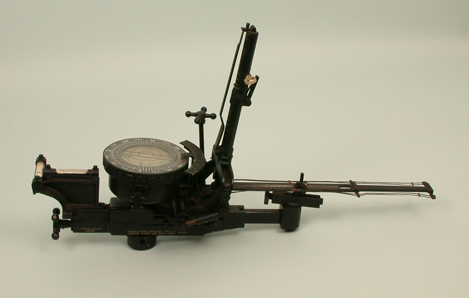
 The post-WWI Mk. IIH was one of a series of Mk. II designs introduced around 1920. Two differences in this "H" model are the prominent spirit level assembly on the left, and the doubled-up drift wires on the right that make it easier for the bomb aimer to measure and correct residual wind drift. More difficult to see is the trail setting screw, which rotates the height bar forward.
In testing in December 1917 at the Scilly Isles air station, in eight bomb runs the CSBS scored two direct hits, and near-misses on all six other runs. Production quickly followed, and by 1918 about 720 had been produced. The Royal Flying Corps (RFC) started using the Mark I sight as soon as supplies were available, and by April 1918 were also fully converted to this type.[1]
For his work on the CSBS and the Drift Sight Wimperis was awarded £2,100 by the Royal Commission on Awards to Inventors.[6]
In the post-war era, work on new bombsights was seriously curtailed, and little new development had taken place by 1930. Several minor variations of the CSBS had been introduced during this period to adapt to higher speeds, higher or lower altitudes, and new types of bombs. These also included a separate adjustment for "trail", the deceleration of the bomb due to drag. At low speeds and altitudes the time between drop and impact was too short for the bombs to reach terminal velocity so the trajectory of the bombs was roughly parabolic. At higher altitudes or forward speeds the bombs would reach terminal long before impact, which had the effect of making the last portion of the flight path more vertical. The trail adjustment, set by dialling in the measured terminal velocity for the bombs being dropped, used a cam to move the height bar forward away from the vertical, reducing the range angle and thereby reducing the range.[7]
Many thousands of CSBSs were sold around the world, and many other sights were developed from the basic idea. In the mid-1930s, the basic CSBS concept was largely universal for production bombsights.[1] The development of more advanced designs like the Norden bombsight was just beginning.
Mk. VII and IX
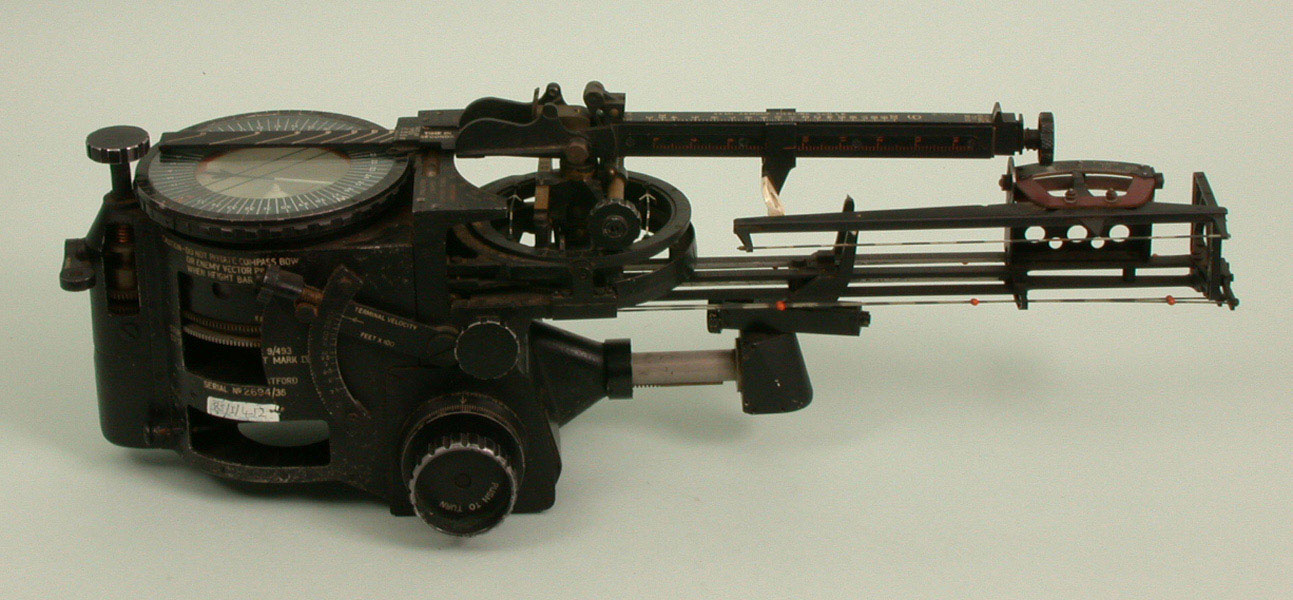
 The more complex Mk. IX and similar Mk. VII versions included adjustments for moving targets (horizontal rings at center) and indirectly measuring drift (assembly on the far right). This example is folded into its stowed position, with the height bar rotated down over the drift bar.
During its evolution prior to the opening of World War II, the CSBS added several new features.
A simple modification found on late models was the "Auxiliary Drift Bar" attachment. This consisted of a single drift wire in a C-shaped clamp that could be moved along the main drift wires, and rotated in relation to them. Prior to the bomb run, the bomb aimer would sight through the backsight toward the Auxiliary Drift wire, and continually rotate the wire until objects on the ground could be seen moving directly along it. This gave the drift angle, which could be used with a separate measurement of the wind speed in order to set up the sight, or used with a variety of wind measuring systems (see below) to avoid moving the sights themselves.[8]
Finally, the later versions used by Coastal Command and the Royal Navy also included a further adjustment, the "Fourth Vector", for attacking moving targets, primarily for use against ships and submarines. This was a fairly complex system of rotating rings and sliders that allowed the bomb aimer to dial in the relative course of the target and its estimated speed. This moved the backsight directly fore and aft, and turning the heading dial adjusted how much the speed dial moved the backsight.[9] As the resulting mechanism was fairly large and complex, the sights were also available with the Fourth Vector removed, denoted with a "*", as in the Mk. IX A*.[10]
Mk. X
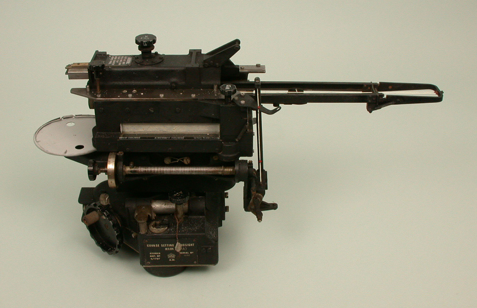
 The Mk. X is a dramatic change from earlier models, removing the direct relationship between the parts and their functions. For instance, altitude is now set via a knob on the left side of the device (far side of this image) read against a rotating scale. This example is missing the compass, normally set on the metal plate on the left.
Prior to the war a major redesign of the CSBS was underway. The new Mk. X replaced the vertical slider used for altitude adjustment with a horizontally-moving backsight at the top of the device, and the entire foresight and drift wire area was made considerably smaller. The calculator and wind drift settings, formerly mounted on top and in front of the large compass at the rear of the earlier models, was moved to the left side of the device and changed in form to make it smaller as well. The compass itself was also smaller. The result was a version of the CSBS that was much smaller than earlier versions.[11]
About 5,000 of the new Mk. X were built and awaiting fitting to aircraft at the opening stages of the war. After the disastrous raid on Wilhelmshaven in 1939, the RAF was forced to abandon daylight attacks and move to night bombing. The Mk. X proved to have very poor visibility at night, and would be difficult to modify to correct this problem. The Mk. X had to be abandoned, and Mk. VII's and Mk. IX's hurriedly re-fit to aircraft.[12] Thus the older versions of the CSBS soldiered on long after it was to be replaced, and remained the primary British bombsight into 1942. The Mk. VII was widely found on slower aircraft and training schools, while the Mk. IX was used in higher speed aircraft.[13] Versions without the Fourth Vector attachment were used in modern tactical designs like the de Havilland Mosquito and Douglas Boston.
Mk. XI
Another problem with all of the existing CSBS designs was that it could only be read correctly with the aircraft absolutely level. This was true especially during the run-up to the drop point, when the sight was used to correct the direction of flight through the use of the drift wires. The biplane bombers the CSBS had been developed for had the ability to slip-turn to a new heading using the rudder only, which made it simple for the pilot to adjust their heading without effecting the aim too much. Most modern monoplanes were subject to an effect known as dutch roll that makes them "hunt" for a time after turning to a new heading. During this time the drift wires were difficult to use, so the entire process of correcting the flight path was greatly extended.[14]
In the aftermath of the Wilhelmshaven raid on 3 September 1939, it was found that the lengthy calculations and bomb run demanded by the CSBS made its aircraft extremely vulnerable to fighter and anti-aircraft artillery. At a pre-arranged meeting on 22 December 1939, Air Chief Marshal Sir Edgar Ludlow-Hewitt made a request for a new bombsight that did not require such a long run into the target, and which would allow the aircraft to manoeuvre throughout the bomb run.[15]
The solution to this problem was well understood within the industry; use gyroscopes to provide a level platform to mount the bombsight on, what would today be known as an inertial platform. However, the large physical size of the CSBS series, especially the long drift bar, made it extremely difficult to mount successfully. A compromise solution was designed as the Mk. XI, which mounted a single drift wire and iron sight on the front of a gyroscope taken from a Sperry artificial horizon that was already common. This provided stabilization in the roll axis, which greatly eased the problem of sighting while maneuvering.[14]
Unfortunately, the new design also removed all of the calculation system of the bombsight in order to make it fit. Instead, the bomb aimer had to use manual slide rule calculators to find the drift and bombing angles, and then set the bombsight to these values. As before, the bombsight was thus unable to quickly adapt to changes in direction or altitude, and in this case was even slower to calculate any such changes. Very few of the Mk. XI designs were produced.[16]
Mk. XII and Mk. XIV, a new approach
Main article: Mark XIV bomb sightAs if these problems were not enough, the RAF found in the training schools that it was all too common for the bomb aimers to dial in an incorrect setting, or forget to update one when conditions changed.[15] It was planned that many of these problems would be solved on the Automatic Bomb Sight (ABS), which had been under development from before the war, and used very simple inputs from the bomb aimer to carry out all the needed calculations. However, the ABS was even larger than the CSBS, so the demand for stabilization mean it would take some time before it could be brought into service. The physicist and scientific advisor Patrick Blackett took up the challenge of fixing all of these problems at once, producing the "Blackett sight" with the Royal Aircraft Establishment.[16][Notes 1]
First, the manual calculator was replaced by an external box operated by a new crew member. The box contained various aircraft instruments and the new operator simply had to keep a series of dials set so their indicators overlapped those on the instruments.[16] This drove the machine to calculate the correct angles, as on the earlier CSBS models, and fed them directly into a remote sighting unit, the "sighting head". The wire sights of the earlier models were replaced by reflector sights indicating the location the bombs would hit if dropped at that instant. As the sighting head lacked the vector computer it was much smaller than earlier models, which allowed it to be easily mounted on a stabilized platform. This allowed the sights to be used even while the aircraft was maneuvering, and required only 10 seconds to "settle".[13]
The addition of a new operator was an obvious problem, and led to the ultimate development of the series, the Mk. XIV. This replaced the manual dials with ones powered by air suction bled from the engines. Before the mission the bomb aimer entered basic information about the target altitude and the bombs being dropped, and periodically updated the wind speed and direction. Everything else was fully automated.[13] Versions were also developed that replaced the altitude measurement with a radar altimeter for low-altitude use, but these Mk. XV and Mk. XVII were not used operationally.[17]
The Mk. XIV was a major advance over the Mk. IX, but service entry was slow. It was not until January 1942 that it was given priority.[13] This was aided by Sperry Gyroscope, who re-designed the system to U.S. production methods. They sub-contracted construction to A.C. Spark Plug who built tens of thousands as the "Sperry T-1".[15] It did not offer the level of accuracy of tachometric bombsights like the Norden, but for night area bombing from medium altitude this was not an issue. The Mk. XIV remained in RAF use until 1965.
SABS
Later in the war the development of the Tallboy and Grand Slam "earthquake bombs" demanded accuracy that even the Mk. XIV could not supply. For this role, the Automatic Bomb Sight was dusted off and mounted to new stabilization platform, producing the Stabilized Automatic Bomb Sight. This complex device was available only in very small numbers from late 1943 on, and used only by specific groups within the RAF.[18]
Description
The late-model CSBS consists of a number of separate devices and calculators attached together in a single bombsight. Like the Drift Sight before it, the CSBS separated each adjustment into a separate input; altitude, airspeed, and the direction and speed of the wind. This led to considerable mechanical complexity, which only grew over time as additional correction factors were added to the design. The following description is based on the Mk. IX as described in A.P.1730A, but will be separated into sections on the basic operation and the later additions.
Crosswind bombing
 Navigation in wind is a case of simple vector addition. Consider an aircraft at point p attempting to approach a target at q, in the presence of a wind represented by the vector b. By setting their heading to the angle of the vector a and flying at an airspeed represented by the length of a, the aircraft will approach r at the ground speed represented by the length of the purple line a+b.
The "bombsight problem" is the need to determine the exact spot in the air where the bombs should be dropped to hit a target on the ground. Due to the acceleration of gravity, bombs follow a roughly parabolic path, the steepness being defined by the forward speed of the aircraft at the instant of release. The distance the bombs travel between being dropped and hitting the ground is a function of that speed and the time to fall, and is referred to as the "range".[19] The bomber attempts to manoeuvre along a line toward the target and then drop the bombs at the instance they are that distance from the target, the "drop point". In the past, aircraft did not have the ability to fly to an arbitrary point in space, and needed to find their location by reference to a point on the ground. Simple trigonometry can calculate the angle that the target would appear at when the aircraft was at the drop point. This is known as the "range angle" or "drop angle", and was typically looked up from a set of pre-computed tables or using a simple mechanical calculator.
In the presence of a cross-wind, flying the aircraft to this point is difficult. As the aircraft flies forward, the wind will push it sideways, away from the drop point. The solution is to calculate the angle that the aircraft should fly in order to balance out this drift, the difference between the "course" and the "heading",[19] similar to the concept known as "crabbing" as used in a crosswind landing. Calculating the proper drift angle is a simple task of basic vector addition, and is commonly carried out on a circular slide rule like the modern E6B. This is a somewhat time consuming process. The CSBS solved this problem by reproducing the basic vector math in a mechanical system. The vectors that would normally be drawn by hand were duplicated in a series of screws, gears and sliding components. By dialling in the four inputs, altitude, airspeed, wind speed and wind direction, the mechanism moved the aiming pippers so they directly represented the required heading and range angle for the current airspeed and altitude.[2]
It should be noted that the wind will also have an effect on the bomb after it leaves the aircraft. However, as bombs are generally well streamlined and have high density, this effect is much smaller in magnitude than the effects on the aircraft itself. For instance, consider a bomber at 20,000 feet altitude dropping a stick of AN-M65 500 lbs General Purpose Bombs. These bombs will take approximately 37 seconds to reach the ground.[20] In a 25 mph wind – 37 ft/s (11 m/s) – the bomb will move about 1,350 ft (410 m) due to the wind's effect on the aircraft's ground speed. In comparison, the effect of the wind after leaving the aircraft would be only 300 ft (91 m).[21]
Basic mechanism
 Labelled diagram of the various parts of the CSBS. Key components are the compass and directional calculator at the rear, drift bar for course correction and airspeed setting extending at the front, and the vertical scale for altitude setting extending vertically.
- Opening the diagram to the right in a separate window will greatly ease the understanding of the following description.
At the rear of the CSBS is a large compass with a slip ring carrying a rotating compass rose known as the "bearing plate". A large knob at the back of the compass, the "milled head", is used to rotate the bearing plate. The bearing plate has lines on it that are used to represent the wind direction during manual calculations. The top of the bearing plate was designed to be drawn on with a chinagraph pencil so it could serve as a general navigation calculator as well.[22] Turning the milled head also rotated the "wind bar", through a geared shaft, to the same angle in order to mechanically represent the wind vector.[23] At the end of the wind bar is the "wind screw knob", which is used to set the wind speed. As the knob is rotated, a plate inside the wind bar moves fore and aft along the direction of the bar.[23]
Extending out in front of the device was the "drift bar", normally forming over 1/2 of the overall length of the device. The drift bar is pivoted at its base, just in front of the compass area, allowing it to rotate to either side. On top of the wind bar, connecting the wind bar to the drift bar, is the "ground speed slider".[24] A pin passing vertically through the wind bar's internal slider to slotted plates in the drift bar and ground speed slider translate the motion of the wind bar into components along and across the axis of the drift bar. Motion across the axis pushes the entire wind bar to the left or right, indicating the proper heading to fly to cancel out the wind drift. Motion along the axis pushes the ground speed slider fore or aft, accounting for the difference between air and ground speed. The ground speed slider also carries the pin-shaped foresights, so as they move they adjust the sighting angle in order to drop the bombs early or late to account for the ground speed.[23]
The motion of the wind bar and wind screw knob accounts for two of the three vectors involved in the windage calculation. The last is the airspeed of the bomber – its absolute direction can be ignored if everything is measured in terms of the direction to the target. The length of this vector is set by the "air speed drum", found on the right side of the main case (or at the back of the device on earlier versions). Turning the air speed knob drives a shaft that pushes the entire wind bar and ground speed slider fore and aft along the drift bar.[25] Once set, the combination of the air speed, wind direction and wind speed provided all of the vector inputs, and the angle of the drift bar and position of the foresight formed the output. The "drift wires" running down either side of the drift bar were used to measure the drift once calculated, to ensure the aircraft was flying along the correct heading to zero out any wind drift.[24]
The bombsight solution is now almost complete, having calculated the ground speed and zeroed out any sideways drift. All that is left is the calculation of the time of fall, which, multiplied by the ground speed, gives the range. The CSBS solves this through the "height bar", which extends vertically from the center of the device where the compass section meets the drift bar. Turning a knob at the top of the height bar (or using a slip fitting on earlier models) moves the "height slider" up or down to set the aircraft's altitude. Once set, the angle between backsights on the height slider and foresights on the ground speed slider indicates the proper range angle, no lookups required.[26] The bomb aimer then sights along this angle and waits for the target to appear, dropping the bombs when it appears under a notch in the backsight.
Although a bomb's trajectory is roughly parabolic, when the bomb is dropped from high altitudes may reach terminal velocity before hitting the ground. This effects the final trajectory in a non-linear fashion, generally making the line of fall more vertical. To account for this a "trail screw" was added on the Mk. II version of the CSBS, which rotated the height bar forward. This had the effect of reducing the range angle, which accounted for the more vertical trajectory of the bombs. This effect only comes into play for high altitudes when the bomb has time to build up speed. Later models of the CSBS, starting with the Mk. VII, used a cam that was driven by both the altitude setting and the trail screw in order to automate the calculation of this effect. Additionally, each aircraft has a slightly different way of measuring altitude that needs adjustment, the CSBS accounted for this effect by including two altitude scales, a linear scale of altitude in orange on the right side of the bar, and any number of white scales on the back that could be clipped onto the sight. The two were used in combination to make adjustments for the altitude of the target over sea level.[27]
Measuring the wind
Although the CSBS automated the calculation of the effects of the wind, it did not automate the measurement of the wind itself. The bombsight manual describes several ways to do this.
One is an adaptation of the method used with the Drift Sight. Prior to approaching the target, the bomb aimer would have the pilot turn onto the expected wind line, and dials in zero wind speed and due "north" wind direction, which points the drift bar straight forward. With the bar in this position, the bomb aimer uses the drift wires to tune out any sideways drift and thereby find the exact wind direction. The bearing plate is rotated to the compass heading and locked, thereby recording the wind direction for future reference. The pilot then turned 90 degrees to one side or the other, placing the wind directly off the side of the aircraft. The bomb aimer then rotated the milled head to the same 90 degrees. At this point the wind speed knob is adjusted, pushing the drift bar sideways until objects on the ground could be seen moving directly along the drift wires. The wind speed is now known and set, and the aircraft can then manoeuvre as it wants with only the milled head needing adjustment.[28]
A later modification to the CSBS, and supplied with most of the Mk. VII and Mk. IX examples, was the "auxiliary drift bar". This was attached at the front of the main drift bar and consisted of a single drift wire mounted on a rotating fixture.[29] This allowed direct measurements of the drift relative to the aircraft path without having to rotate the main drift bar or fly along a given heading. This did not directly measure the wind speed, which had to be measured using alternate means, typically by timing ground objects against small beads on the drift wires.[30]
Any number of wind measurements or navigation calculations could be carried out on the compass face using the "wind gauge bar". This was normally stowed folded against the back of the height bar, but could be rotated down and to the rear to lie over the compass. The "cursor" slid along the wind bar, allowing the bomb aimer to measure different airspeeds or times. A small scale on the cursor allowed for the conversion of indicated air speed to true air speed, which differs depending on altitude. A small ring on the right side of the cursor was used to accurately place markings on the compass using the grease pencil. A holder for the pencil and a sharpener blade were attached on the left side of the case.[31]
The third method of determining the wind is used in conjunction with the wind gauge bar. The aircraft is flown on three different headings, typically 120 degrees apart, and the time for the aircraft to travel a certain distance was measured with the timing beads. The bearing plate was rotated to match the compass heading of each leg, and the cursor was moved along the bar to draw a line on the bearing plate along that direction. After three such measurements a small triangle was formed. The aircraft then turned onto the bomb line. Using the drift angle measured from the auxiliary drift bar, the compass was rotated to that drift angle, and the cursor moved so it lay above the center of the triangle. This indicated the direction and speed of the wind.[30]
Other details
Levelling the bombsight was required before any use. The bombsight included two spirit levels for this, and was mounted to a friction-set ball so it could be rotated in any direction.[32] This allowed it to be mounted to the side of aircraft like the Supermarine Walrus,[33] or to the floor of dedicated bomber aircraft like the Bristol Blenheim. As the most common change in angle is due to changes in aircraft trim with changes in airspeed, earlier models featured a prominent setting for correcting the fore-aft angle of the sight, which can be seen on the left side of pre-Mk. VII models in the images above.
Naval versions of the Mk. VII and IX, and most supplied to Bomber Command as well, included an additional adjustment for moving targets. Attacking a moving target is similar to the basic concept for correcting for wind, although, unlike wind, the target's movement may be significant even after the bomb is dropped. The CSBS accounted for this through the use of the "enemy vector mechanism" or "fourth vector", which was similar to the wind mechanism but operated at the origin of the drift bar instead of a point located along it. Setting the "enemy speed screw" or "enemy direction knob" moved a mechanism similar to the wind bar, but the movement along the track moved the entire height bar fore or aft.[34]
References
Notes
- ^ Although the Mk. XII and XIV were dramatically different from the CSBS designs they replaced and are generally considered to be new and unrelated designs, the Air Ministry decided to place them in the same sequence of development, giving them the next model number in the existing series.
Citations
- ^ a b c d e f Goulter 1996, p. 27.
- ^ a b c Abbatiello 2006, p. 32.
- ^ Goulter 1996, p. 26.
- ^ a b Abbatiello 2006, p. 31.
- ^ Harry Egerton Wimperis, "A Primer of Air Navigation", Van Nostrand, 1920
- ^ "Awards for War Inventions" Flight 15 January 1925 p33
- ^ AP1730 1943, Chapter 4 §30.
- ^ AP1730 1943, Chapter 4 §81.
- ^ AP1730 1943, Chapter 4 Figure 5.
- ^ "Mk. IX A*"
- ^ Compare images of the MK. IX mounted to the Supermarine Walrus, and the Mk. X on its stabilizer.
- ^ Major 2001.
- ^ a b c d Harris 1995, p. 100.
- ^ a b SD719 1952, p. 282.
- ^ a b c T-1 2001.
- ^ a b c SD719 1952, p. 283.
- ^ SD719 1952, p. 284.
- ^ See entry for 11/12 November 1943, "Royal Air Force Bomber Command 60th Anniversary: Campaign Diary November 1943", RAF
- ^ a b See diagrams at the bottom of Torrey, p. 70
- ^ Allan Raymond, "How Our Bombsight Solves Problems", Popular Science, December 1943, p. 119
- ^ "Terminal Ballistic Data, Volume I: Bombing", US Army Office of the Chief of Ordnance, August 1944, p. 23
- ^ AP1730 1943, Chapter 4 §12–15.
- ^ a b c AP1730 1943, Chapter 4 §38–40.
- ^ a b AP1730 1943, Chapter 4 §41.
- ^ AP1730 1943, Chapter 4 §25–32.
- ^ AP1730 1943, Chapter 4 §59–64.
- ^ AP1730 1943, Chapter 4 §62–63.
- ^ AP1730 1943, Chapter 4 §88.
- ^ AP1730 1943, Chapter 4 §46–49.
- ^ a b AP1730 1943, Chapter 4 §94.
- ^ AP1730 1943, Chapter 4 §65–70.
- ^ AP1730 1943, Chapter 4 §5.
- ^ See the selection of images on this site on the Supermarine Walrus for details of the mounting system, and the somewhat unwieldily result.
- ^ AP1730 1943, Chapter 4 §50–59.
Bibliography
- AP1730, "Air Publication A.P.1730A, Volume 1: Bomb Sights", Air Ministry, 1943
- SD719, "Armament, Volume I; Bombs and Bombing Equipment", Air Ministry, 1952
- Christina Goulter, "A forgotten offensive: Royal Air Force Coastal Command's anti-shipping campaign, 1940–1945", Routledge, 1995
- Henry Black (Major), "Major Bomb Sights Used in WW2 by RAF Bomber Command", 2001
- Henry Black (T-1), "The T1- Bomb Sight Story", 26 July 2001
- John Abbatiello, "Anti-submarine warfare in World War I: British naval aviation and the defeat of the U-Boats", Taylor & Francis, 2006
- Sir Arthur Travers Harris, "Despatch on war operations, 23rd February, 1942, to 8th May, 1945", Routledge, 1995. See Appendix C, Section VII
- Volta Torrey, "How the Norden Bombsight Does Its Job", Popular Science, June 1945, pp. 70–73, 220, 224, 228, 232
Further reading
- An image of the Mk. IX mounted in a Mosquito can be found in Ian Thirsk, "De Havilland Mosquito: An Illustrated History", MBI Publishing Company, 2006, p. 68
Categories:- Optical bombsights
- 1917 introductions


Wikimedia Foundation. 2010.