- Corrected firing data
-
Corrected firing data was a term used in the U.S. Coast Artillery to refer to firing data (range and azimuth to the target) that had been corrected[1] for various "non-standard conditions." This could include corrections to range and corrections to azimuth or deflection.[2] Corrections could be made, variously, for the following factors:
- Variations in muzzle velocity (including the results of variations in temperature of powder)
- Variations in atmospheric density
- Variations in atmospheric temperature
- Height of site (taking account of the level of the tide)
- Variations in weight of projectile
- Travel of the target during the time of the projectile's flight.
- Wind
- Rotation of the earth (for long range guns)
- Drift.[3]
The uncorrected firing data, to which such corrections were applied, were those derived, for instance, from using a plotting board to track the position of an observed target (e.g., a ship) and the range and azimuth to that target from the guns of a battery.
Contents
How the Corrections Were Made
Meteorological Data
Several of the common corrections depended on meteorological data. For this reason, each Coast Artillery fort or fire command maintained its own meteorological station which transmitted an hourly meteorological message[4] to the entire command whenever firing was anticipated. This message included a series of five- and seven-digit data blocks that reported on the temperature at a given altitude, followed by the wind speed, direction, and ballistic density of the air at each of 11 different altitude bands, running from the surface up through 30,000 ft. The higher altitude readings were needed for firings of the 12-inch coast defense mortars, which sent their shells on very high trajectories.
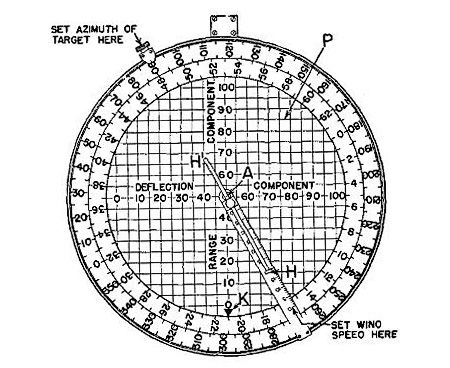
Once data were available on wind speed and direction, a circular slide rule-like device called a wind component indicator (see the left-most image below) was used to figure out the components of the wind that affected either the range or the deflection (direction) of the shells fired. This device yielded index numbers that were either fed to the plotting room and used to correct readings on a plotting board, were used as input to a deflection board (see below) or were telephoned to the batteries and used by gun crews to make offsets directly on the range wheels or sights of the guns themselves.
Using the Range Correction and Deflection Boards
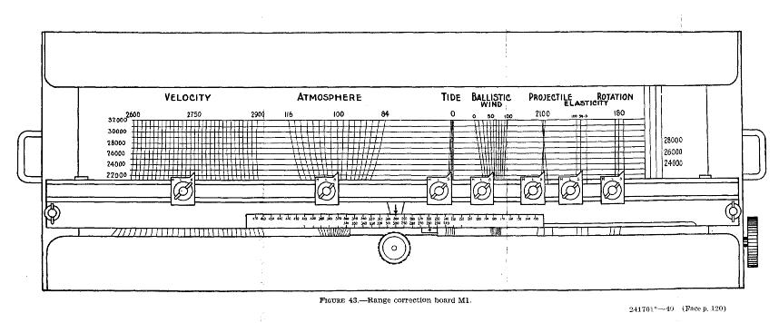
The range correction board is pictured below.[5] This was a tabletop device (that resembled a 1940s-vintage wide-carriage mechanical adding machine, without the operating arm on the side)[6] that was used to figure out the individual corrections that might be required for factors #1 through #7 above and to cumulate these. The result from the range correction board was fed to a slide rule-like device called a percentage corrector to obtain the corrections (if any) to be sent to the gun/s. The range correction board made use of a paper chart that was rolled onto its working surface and offered non-standard curves from which corrections could be read off. This chart had to be specific to the combination of gun, power charge, and projectile in use at the time. Values for the individual factors (#1 through #7 above) had to be obtained by plotting room personnel from battery officers or from the hourly meteorological message.[7]
Also pictured below is the deflection board, used to correct for any of the factors #6 through #9 above. The Model 1905 board is shown in the two images at right below.[8] This device had a movable T-square and also a movable brass frame (or platen), both of which could be slid back and forth independently across three scales that ran across its base. The protractor-like portion of the platen carried the multiplying scale, which was sometimes used if the battery had missed the chance to fire at the proper interval and was forced to wait until the next interval.[9] Also affixed to the base of the board was a truncated arc (the wind arc and scale, at the left side of the board, which was used to set up the board for the wind speed and direction reported in the meteorological message (see above).
Proper alignment and rotation of the inter-related scales and arms enabled corrections to be read off the three different scales that ran horizontally across the bottom of the board (the travel scale, the deflection scale, and the azimuth correction scale). Even then, however, the use of the device was complicated, since it yielded reference numbers that had to be fed back to the operators of the plotting board before being fed to the guns.
Like many other pieces of Coast Artillery fire control equipment, the deflection board was a mechanical analog computer that used methods of similar triangles to solve the problems of correcting fire for wind speed and direction, drift of the projectile, and angular travel of the target during the observing interval.[10]
 A wind component indicator used to translate data on wind speed and direction into range and deflection (azimuth) corrections for Coast Artillery guns.
 Rendering of the face of a range correction board, a mechanical, analog device that sat on a tabletop and cumulated corrections in range for firing Coast Artillery guns.
 A deflection board M1905 is shown in this 1910 photo, which labels many of its components.
 This 1940 drawing of the deflection board M1905 shown at left is included because it more clearly shows some of the scales used on the board.
References
- ^ In Coast Artillery parlance, the term "correction" usually referred to changes in estimated range or deflection (direction) that were made prior to firing. The term "adjustment" usually referred to changes that were made after a shot had been fired and were used to modify the aim of the gun/s for the next shot. Adjustments were usually made by observing and plotting the fall (splashes) of the shells fired and reporting by how much they were left or right in azimuth or over or under in range.
- ^ See Chapter 4, "FM 4-15 Coast Artillery Field Manual-Seacoast Artillery Fire Control and Position Finding," U.S. War Department, Government Printing Office, Washington, 1940.
- ^ Drift refers to "the divergence of the projectile from the plane of departure due to its rotation, its ballistic character, and the resistance of air. It is generally in the direction of rotation...." See "The Service of Coast Artillery," Frank T. Hines and Franklin Ward, Goodenough & Woglom, New York, 1910, p. 21.
- ^ For the details of this message and how its data were handled, see Supra, Note 2, pp. 113-116.
- ^ A more complete description of using the board is contained at Supra, Note 2, p. 119 ff.
- ^ This photo of a plotting room shows a range correction board in use (on the left side of the table, at rear).
- ^ Since precise measurements of muzzle velocity (factor #1) often could not be made, estimates were used, based upon the size of the powder charge being fired and the characteristics of the individual gun being used.
- ^ This board looked a good deal like the Whistler-Hearn plotting board, which in fact it was designed to complement.
- ^ For a description of observation and firing intervals, see the article on the overall system of fire control in the Coast Artillery.
- ^ A description of the steps involved in using this board can be seen at Supra, Note 2, p. 132ff.
Categories:


Wikimedia Foundation. 2010.