- Compact linear Fresnel reflector
-
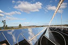 Fig.1: Example of a Traditional linear Fresnel reflector with one absorber.
A compact linear Fresnel reflector (CLFR) – also referred to as a concentrating linear Fresnel reflector - is a specific type of linear Fresnel reflector (LFR) technology. Linear Fresnel reflectors use long, thin segments of mirrors to focus sunlight onto a fixed absorber located at a common focal point of the reflectors. These mirrors are capable of concentrating the sun’s energy to approximately 30 times its normal intensity.[1] This concentrated energy is transferred through the absorber into some thermal fluid (this is typically oil capable of maintaining liquid state at very high temperatures). The fluid then goes through a heat exchanger to power a steam generator. As opposed to traditional LFR’s, the CLFR utilizes multiple absorbers within the vicinity of the mirrors.
Contents
History
The first linear Fresnel reflector was developed in Italy in 1961 by Giovanni Francia of the University of Genoa.[2] Francia demonstrated that such a system could create elevated temperatures capable of making a fluid do work. The technology was further investigated by companies such as the FMC Corporation during the 1973 oil crisis, but remained relatively untouched until the early 1990s.[1] In 1993, the first CLFR was developed at the University of Sydney in 1993 and patented in 1995. In 1999, the CLFR design was enhanced by the introduction of the advanced absorber.[2] In 2003 the concept was extended to 3D geometry.[3] Research published in 2010 showed that higher concentrations and / or higher acceptance angles could be obtained by using nonimaging optics to explore different degrees of freedom in the system such as varying the size and curvature of the heliostats, placing them at a varying height (on a wave-shape curve) and combining the resulting primary with nonimaging secondaries.[4]
Design
Reflectors
The reflectors are located at the base of the system and converge the sun’s rays into the absorber. A key component that makes all LFR’s more advantageous than traditional parabolic trough mirror systems is the use of "Fresnel reflectors". These reflectors make use of the Fresnel lens effect, which allows for a concentrating mirror with a large aperture and short focal length while simultaneously reducing the volume of material required for the reflector. This greatly reduces the system’s cost since sagged-glass parabolic reflectors are typically very expensive.[2] It should be noted, however, that in recent years thin-film nanotechnology has significantly reduced the cost of parabolic mirrors.[5]
A major challenge that must be addressed in any solar concentrating technology is the changing intensity of the incident rays (the rays of sunlight striking the mirrors) as the sun progresses throughout the day. The reflectors of a CLFR are typically aligned in a north-south orientation and turn about a single axis using a computer controlled solar tracker system.[6] This allows the system to maintain the proper angle of incidence between the sun’s rays and the mirrors, thereby optimizing energy transfer.
Absorbers
The absorber is located at the focal point of the mirrors. It runs parallel to and above the reflector segments to transport radiation into some working thermal fluid. The basic design of the absorber for the CLFR system is an inverted air cavity with a glass cover enclosing insulated steam tubes, shown in Fig.2. This design has been demonstrated to be simple and cost effective with good optical and thermal performance.[1]
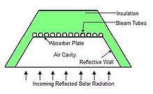 Fig.2: Incident solar rays are concentrated on insulated steam tubes to heat working thermal fluid
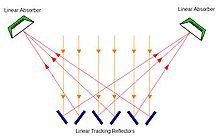 Fig.3: CLFR solar systems alternate the inclination of their mirrors to focus solar energy on multiple absorbers, improving system efficiency and reducing overall cost.
For optimum performance of the CLFR, several design factors of the absorber must be optimized.
- First, heat transfer between the absorber and the thermal fluid must be maximized.[1] This relies on the surface of the steam tubes being selective. A selective surface optimizes the ratio of energy absorbed to energy emitted. Acceptable surfaces generally absorb 96% of incident radiation while emitting only 7% through infra-red radiation.[7] Electro-chemically deposited black chrome is generally used for its ample performance and ability to withstand high temperatures.[1]
- Second, the absorber must be designed so that the temperature distribution across the selective surface is uniform. Non-uniform temperature distribution leads to accelerated degradation of the surface. Typically, a uniform temperature of 300 °C (573 K; 572 °F) is desired.[1] Uniform distributions are obtained by changing absorber parameters such as the thickness of insulation above the plate, the size of the aperture of the absorber and the shape and depth of the air cavity.
As opposed to the traditional LFR, the CLFR makes use of multiple absorbers within the vicinity of its mirrors. These additional absorbers allow the mirrors to alternate their inclination, as illustrated in Fig. 3. This arrangement is advantageous for several reasons.
- First, alternating inclinations minimize the effect of reflectors blocking adjacent reflectors’ access to sunlight, thereby improving the system's efficiency.
- Second, multiple absorbers minimize the amount of ground space required for installation. This in turn reduces cost to procure and prepare the land.[1]
- Finally, having the panels in close proximity reduces the length of absorber lines, which reduces both thermal losses through the absorber lines and overall cost for the system.
Applications
In March 2009, the German company Novatec Biosol constructed the Fresnel solar power plant known as PE 1. The solar thermal power plant is based on CLFR technology and has an electrical capacity of 1.4 MW. PE 1 comprises a solar boiler with mirror surface of approximately 18,000 m2 (1.8 ha; 4.4 acres).[8] The steam is generated by concentrating sunlight directly onto a linear receiver, which is 7.40 metres (24.28 ft) above the ground.[8] An absorber tube is positioned in the focal line of the mirror field where water is heated into 270 °C (543 K; 518 °F) saturated steam. This steam in turn powers a generator.[8]
The commercial success of the PE 1 has led Novatec Biosol to design a 30 MW solar power plant known as PE 2. PE 2 will be constructed in Murcia, Spain in 2010. Novatec Biosol has also obtained permits for another 60 MW of related projects.[8]
In April 2008, the solar thermal company AREVA Solar (Ausra) opened a large factory in Las Vegas, Nevada that will produce linear Fresnel reflectors.[9] The factory will be capable of producing enough solar collectors to provide 200 MW of power per month.[10]
AREVA Solar (Ausra) has finished construction of the 5 MW Kimberlina Solar Thermal Energy plant in Bakersfield, California.[10] This is the first commercial linear Fresnel reflector plant in the United States. The solar collectors were produced at the Ausra factory in Las Vegas.
AREVA Solar (Ausra) also built and operates a linear fresnel reflector plant in New South Wales, Australia. This reflector plant supplements the 2,000 MW coal-fired Liddell Power Station.[11] The power generated by the solar thermal steam system is used to provide electricity for the plant's operation, offsetting the plant’s internal power usage.
Solar Fire, an appropriate technology NGO in India, has developed an open source design for a small, manually operated, 12 kW peak Fresnel concentrator that generates temperatures up to 750 °C (1,020 K; 1,380 °F) and can be used for various thermal applications including steam powered electricity generation.[12][13]
See also
References
- ^ a b c d e f g Dey, C.J. (2004). "Heat transfer aspect of an elevated linear absorber". Solar Energy 76 (2004): 243–249.
- ^ a b c Mills, D.R. (2004). "Advances in solar thermal electricity technology". Solar Energy 76 (2004): 19–31.
- ^ Philipp Schramek and David R. Mills, Multi-tower solar array, Solar Energy 75, pp. 249-260, 2003
- ^ Julio Chaves and Manuel Collares-Pereira, Etendue-matched two-stage concentrators with multiple receivers, Solar Energy 84, pp. 196-207, 2010
- ^ United States Department of Energy (2009). "Solar Energy Technologies Program: Concentrating Solar Power" (PDF). http://www.eere.energy.gov/solar/pdfs/46661.pdf.
- ^ Mills, D.R.; Morrison (2000). "Compact linear Fresnel reflector solar thermal power plants". Solar Energy 68 (2000): 263–283.
- ^ "SolMax, Solar Selective Surface Foil" (PDF). http://www.eisgroupltd.com/solmax_binder11.pdf.
- ^ a b c d "World First in Solar Power Plant Technology". http://www.novatec-biosol.com/index.php?article_id=43&clang=1.
- ^ Schlesinger, V. (2008-July), "Solar Thermal Power Just Got Hotter", Plenty Magazine
- ^ a b "Ausra Technology". http://www.ausra.com/technology/experience.html.
- ^ Jahanshahi, M. (2008-August), "Liddell thermal power station – greening coal-fired power", Ecogeneration
- ^ Parmar, Vijaysinh (Feb 5, 2011). "'Solar fire' to quench energy thirst at grassroots". Times of India. http://timesofindia.indiatimes.com/city/rajkot/CCIS-0502-Solar-fire-to-quench-energy-thirst-at-grassroots/articleshow/7433669.cms. Retrieved May 15, 2011.
- ^ "Solar Fire P32 - Solar Fire Project". solarfire.org. 2011 [last update]. http://www.solarfire.org/Solar-Fire-P32. Retrieved May 15, 2011.
Categories:


Wikimedia Foundation. 2010.