- Formwork
-
Animation depicting construction of multi-story building using aluminum handset formwork.

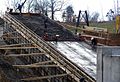
 Modular steel frame formwork for a foundation
 Timber formwork for a concrete column
 Re-usable Plastic-Formwork for mass housing
 Sketch of the side view of traditional timber formwork used to form a flight of stairs
 Placing a formwork component
Formwork is the term given to either temporary or permanent molds into which concrete or similar materials are poured. In the context of concrete construction, the falsework supports the shuttering moulds.
Contents
Formwork and concrete form types
Formwork comes in several types:
- Traditional timber formwork. The formwork is built on site out of timber and plywood or moisture-resistant particleboard. It is easy to produce but time-consuming for larger structures, and the plywood facing has a relatively short lifespan. It is still used extensively where the labour costs are lower than the costs for procuring re-usable formwork. It is also the most flexible type of formwork, so even where other systems are in use, complicated sections may use it.
- Engineered Formwork System. This formwork is built out of prefabricated modules with a metal frame (usually steel or aluminium) and covered on the application (concrete) side with material having the wanted surface structure (steel, aluminum, timber, etc.). The two major advantages of formwork systems, compared to traditional timber formwork, are speed of construction (modular systems pin, clip, or screw together quickly) and lower life-cycle costs (barring major force, the frame is almost indestructible, while the covering if made of wood; may have to be replaced after a few - or a few dozen - uses, but if the covering is made with steel or aluminium the form can achieve up to two thousand uses depending on care and the applications).
- Re-usable plastic formwork. These interlocking and modular systems are used to build widely variable, but relatively simple, concrete structures. The panels are lightweight and very robust. They are especially suited for low-cost, mass housing schemes.
- Permanent Insulated Formwork. This formwork is assembled on site, usually out of insulating concrete forms (ICF). The formwork stays in place after the concrete has cured, and may provide advantages in terms of speed, strength, superior thermal and acoustic insulation, space to run utilities within the EPS layer, and integrated furring strip for cladding finishes.
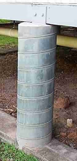
- Stay-In-Place structural formwork systems. This formwork is assembled on site, usually out of prefabricated fiber-reinforced plastic forms. These are in the shape of hollow tubes, and are usually used for columns and piers. The formwork stays in place after the concrete has cured and acts as axial and shear reinforcement, as well as serving to confine the concrete and prevent against environmental effects, such as corrosion and freeze-thaw cycles.
Slab formwork (deck formwork)
 Pantheon dome
 Schematic sketch of traditional formwork
 Modular formwork with deck for housing project in Chile
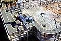
 Steel and Plywood Formwork for Poured in Place Concrete Foundation
History
Some of the earliest examples of concrete slabs were built by Roman engineers. Because concrete is quite strong in resisting compressive loads, but has relatively poor Tensile or torsional strength, these early structures consisted of arches, vaults and domes. The most notable concrete structure from this period is the Pantheon in Rome. To mould these structure, temporary scaffolding and formwork or falsework was built in the future shape of the structure. These building techniques were not isolated to pouring concrete, but were and are widely used in Masonry. Because of the complexity and the limited production capacity of the building material, concrete’s rise as a favored building material did not occur until the invention of Portland cement (and developments by the Edison Portland Cement Company) and reinforced concrete.
Timber beam slab formwork
Similar to the traditional method, but stringers and joist are replaced with engineered wood beams and supports are replaced with metal props. This makes this method more systematic and reusable.
Traditional slab formwork
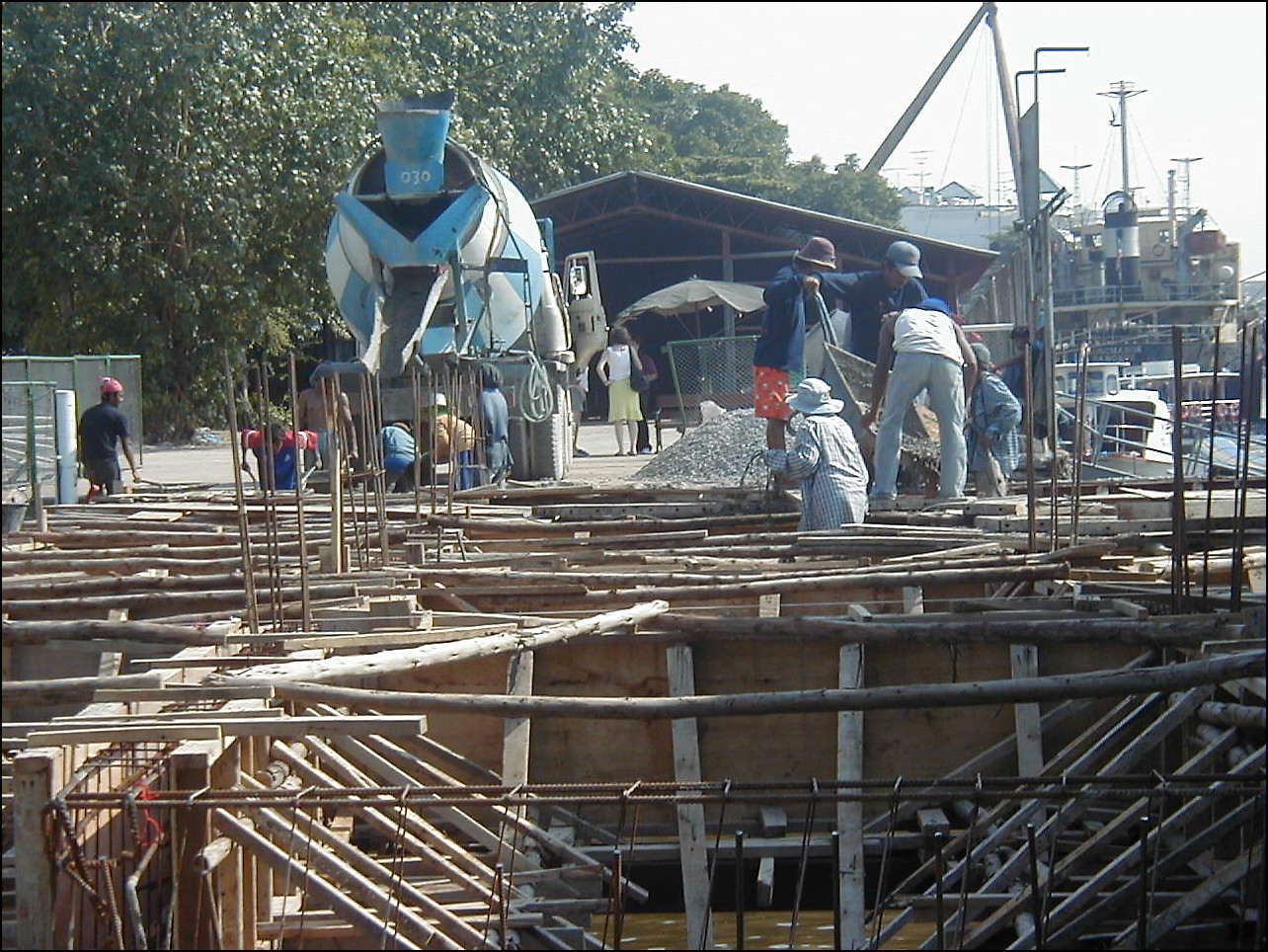
 Traditional timber formwork on a jetty in Bangkok
On the dawn of the rival of concrete in slab structures, building techniques for the temporary structures were derived again from masonry and carpentry. The traditional slab formwork technique consists of supports out of lumber or young tree trunks, that support rows of stringers assembled roughly 3 to 6 feet or 1 to 2 metres apart, depending on thickness of slab. Between these stringers, joists are positioned roughly 12 inches, 30 centimeters apart upon which boards or plywood are placed. The stringers and joists are usually 4 by 4 inch or 4 by 6 inch lumber. The most common imperial plywood thickness is ¾ inch and the most common metric thickness is 21 mm.
Metal beam slab formwork
Similar to the traditional method, but stringers and joist are replaced with aluminium forming systems or steel beams and supports are replaced with metal props. This also makes this method more systematic and reusable.
 Hand setting modular aluminum deck formwork
 Handset modular aluminum formwork
Modular slab formwork
These systems consist of prefabricated timber, steel or aluminum beams and formwork modules. Modules are often no larger than 3 to 6 feet or 1 to 2 metres in size. The beams and formwork are typically set by hand and pinned, clipped, or screwed together. The advantages of a modular system are: does not require a crane to place the formwork, speed of construction with unskilled labor, formwork modules can be removed after concrete sets leaving only beams in place prior to achieving design strength.
Table or flying form systems
United States Patent 4036466.
These systems consist of slab formwork "tables" that are reused on multiple stories of a building without being dismantled. The assembled sections are either lifted per elevator or "flown" by crane from one story to the next. Once in position the gaps between the tables or table and wall are filled with "fillers". They vary in shape and size as well as their building material. The use of these systems can greatly reduce the time and manual labor involved in setting and striking the formwork. Their advantages are best utilized by large area and simple structures. It is also common for architects and engineers to design building around one of these systems.
 Flying formwork tables with aluminium and timber joists. The tables are supported by shoes attached to previously poured columns and walls
Structure
A table is built pretty much the same way as a beam formwork but the single parts of this system are connected together in a way that makes them transportable. The most common sheathing is plywood, but steel and fiberglass are also in use. The joists are either made from timber, wood I-beams, aluminium or steel. The Stringers are sometimes made of wood I-beams but usually from steel channels. These are fastened together (screwed, weld or bolted) to become a "duck". These decks are usually rectangular but can also be other shapes.Afcons Infrastructure Limited
Support
All support systems have to be height adjustable to allow the formwork to be placed at the correct height and to be removed after the concrete is cured. Normally adjustable metal props similar to (or the same as) those used by beam slab formwork are used to support these systems. Some systems combine stringers and supports into steel or aluminum trusses. Yet other systems use metal frame shoring towers, which the decks are attached to. Another common method is to attach the formwork decks to previously cast walls or columns, thus eradicating the use of vertical props altogether. In this method, adjustable support shoes are bolted through holes (sometimes tie holes) or attached to cast anchors.
Size
The size of these tables can vary from 70 to 1,500 square feet (6.5 to 140 m2). There are two general approaches in this system.
- Crane handled: this approach consists of assembling or producing the tables with a large formwork area that can only be moved up a level by crane. Typical widths can be 15, 18 or 20 ft. or 5 to 7 metres but their width can be limited, so that it is possible to transport them assembled, without having to pay for an oversize load. The length vary and can be up to 100 ft. (or more) depending on the crane capacity. After the concrete is cured, the decks are lowered and moved with rollers or trolleys to the edge of the building. From then on the protruding side of the table is lifted by crane whiles the rest of the table is rolled out of the building. After the centre of gravity is outside of the building the table reattached to another crane and flown to the next level or position.
This technique is fairly common in the United States and east Asian countries. The advantages of this approach are the further reduction of manual labour time and cost per area of slab and a simple and systematic building technique. The disadvantages of this approach are the necessary high lifting capacity of building site cranes, additional expensive crane time, higher material costs and little flexibility.
- Crane fork or elevator handled:
 Formwork tables in use at a building site with more complicated structural features
By this approach the tables are limited in size and weight. Typical widths are between 6 to 10 ft or 2 to 3 meters, typical lengths are between 12 and 20 ft or 4 to 7 metres, though table sizes may vary in size and form. The major distinction of this approach is that the tables are lifted either with a crane transport fork or by material platform elevators attached to the side of the building. They are usually transported horizontally to the elevator or crane lifting platform singlehandedly with shifting trolleys depending on their size and construction. Final positioning adjustments can be made by trolley. This technique enjoys popularity in the US, Europe and generally in high labor cost countries. The advantages of this approach in comparison to beam formwork or modular formwork is a further reduction of labor time and cost. Smaller tables are generally easier to customize around geometrically complicated buildings, (round or non rectangular) or to form around columns in comparison to their large counterparts. The disadvantages of this approach are the higher material costs and increased crane time (if lifted with crane fork).
Cassette formwork
See structural coffer.
Usage
For removable forms, once the concrete has been poured into formwork and has set (or cured), the formwork is struck or stripped (removed) to expose the finished concrete. The time between pouring and formwork stripping depends on the job specifications, the cure required, and whether the form is supporting any weight, but is usually at least 24 hours after the pour is completed. For example, the California Department of Transportation requires the forms to be in place for 1–7 days after pouring,[1] while the Washington State Department of Transportation requires the forms to stay in place for 3 days with a damp blanket on the outside.[2]
 Formwork stripped exposing the set concrete
Spectacular accidents have occurred when the forms were either removed too soon or had been under-designed to carry the load imposed by the weight of the uncured concrete. Less critical and much more common (though no less embarrassing and often costly) are those cases in which underdersigned formwork bends or breaks during the filling process (especially if filled with a high-pressure concrete pump). This then results in fresh concrete escaping out of the formwork in a form blowout, often in large quantities.
Concrete exerts less pressure against the forms as it hardens, so forms are usually designed to withstand a number of feet per hour of pour rate to give the concrete at the bottom time to firm up. For example, wall or column forms are commonly designed for a pour rate between 4–8 ft/hr.[citation needed] The hardening is an asymptotic process, meaning that most of the final strength will be achieved after a short time, though some further hardening can occur depending on the cement type and admixtures.
Wet concrete also applies hydrostatic pressure to formwork. The pressure at the bottom of the form is therefore greater than at the top. In the illustration of the column formwork to the right, the 'column clamps' are closer together at the bottom. Note that the column is braced with steel adjustable 'formwork props' and uses 20 mm 'through bolts' to further support the long side of the column.
-

Re-useable Plastic-Formwork designed for mass housing projects.
-
Coal tunnel constructed using handset aluminum concrete forms.
-
Concrete pool construction using aluminum concrete forms.
-

Soffit formwork to a flight of concrete stairs.
-

Stair formwork showing the use of strongbacks to support the riser shutters.
-

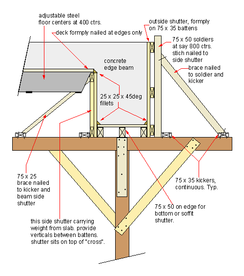
Sketch showing the use timber props for beam forms.
-

Coal silo construction using radius concrete formwork.
-

Detail of an alternative to column clamps for larger columns. Twin steel walers and tie bolts, as used in wall forms.
-

An example of permanent formwork. A column using spiral ducting.
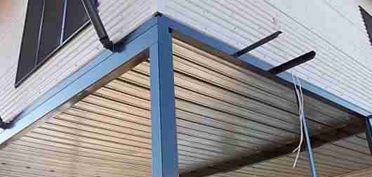
-

An example of permanent formwork, a suspended house slab on roll formed galvanized steel. The formwork in this case is also structural, being bonded to the slab.
-
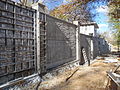
Concrete fence construction using ashlar stone aluminum concrete forms.
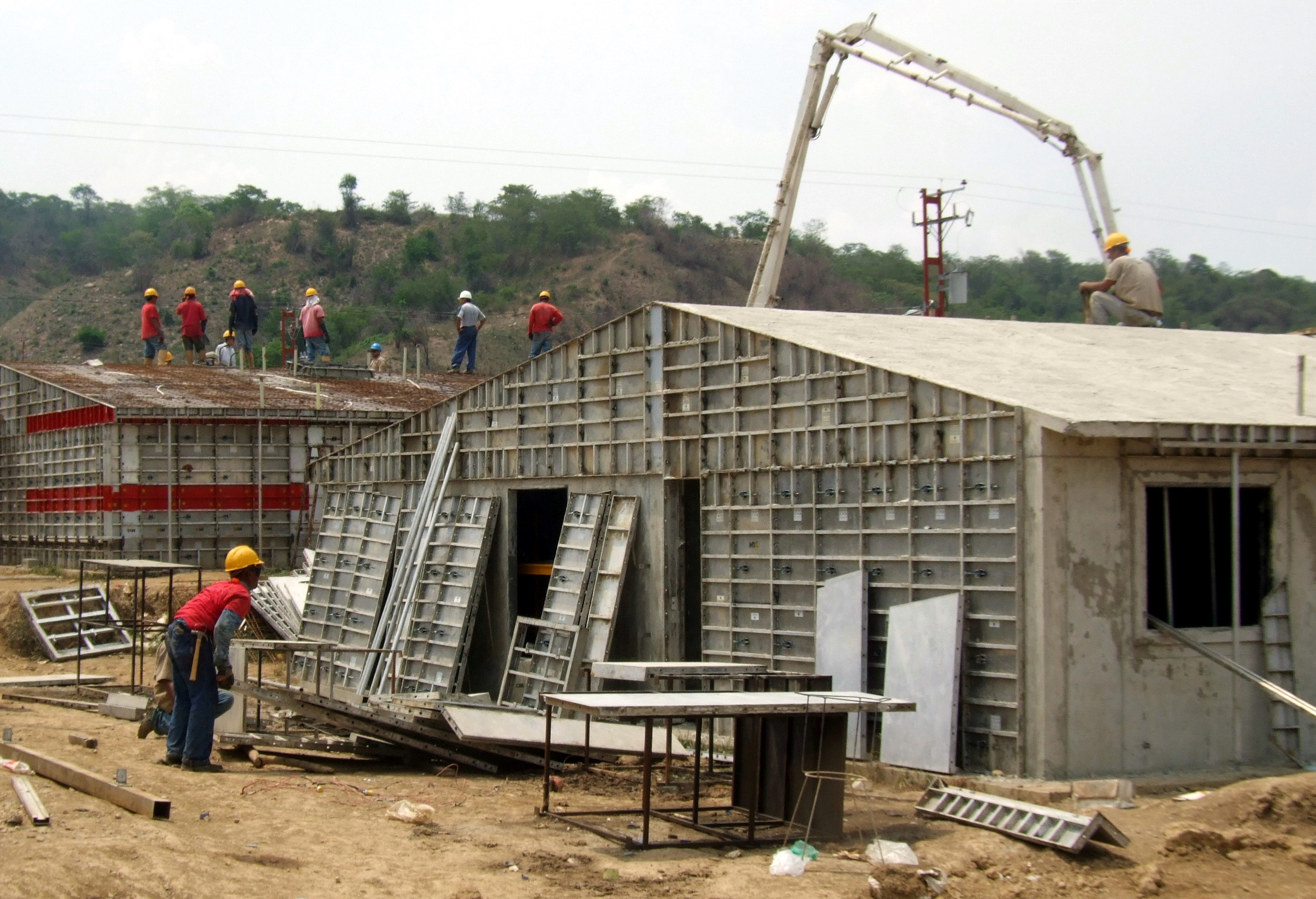
-

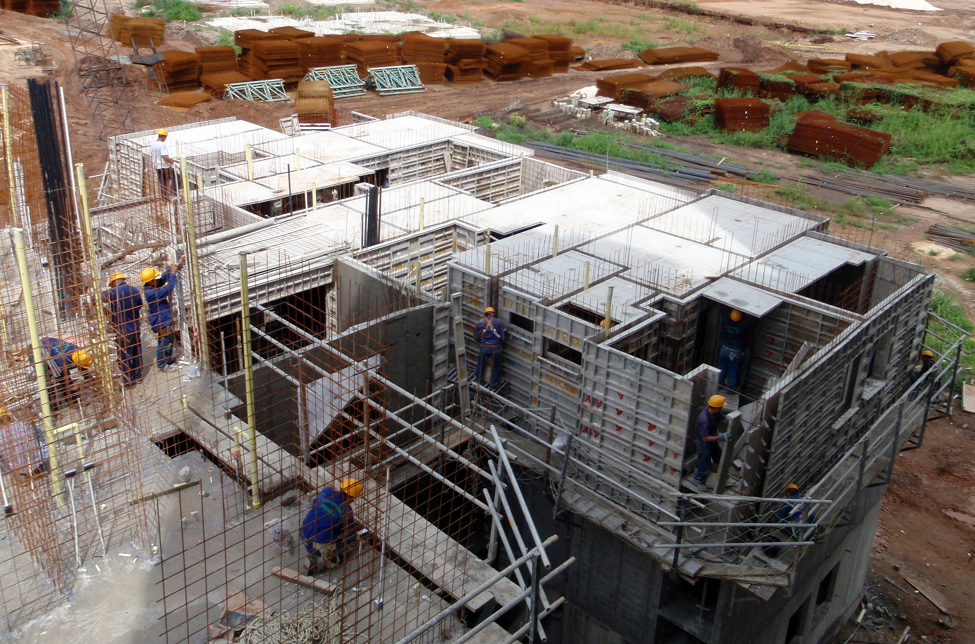
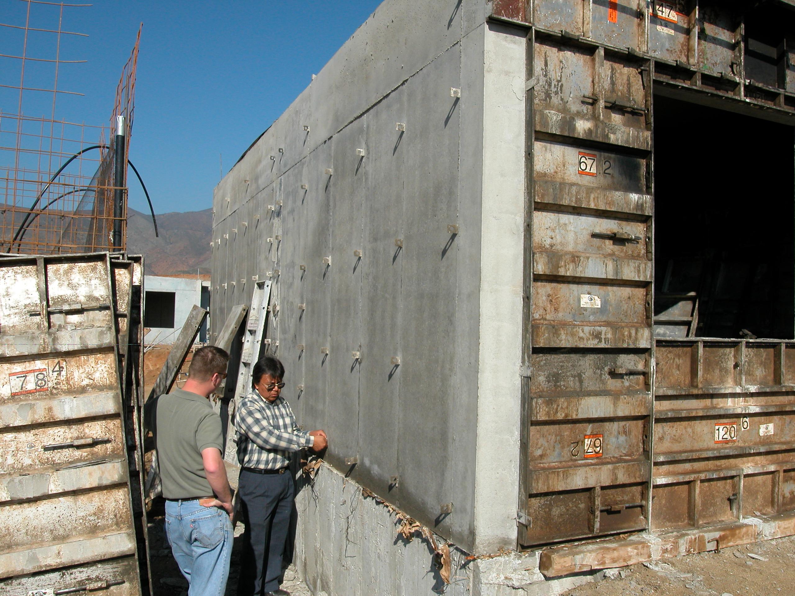
Concrete housing construction in Venezuela using aluminum concrete formwork.
-

Concrete construction in Brazil using handset aluminum concrete formwork.
See also
- Moladi (Plastic Formwork System)
- Climbing formwork (formwork that climbs up the rising building during the construction)
- Concrete cover (depth of the concrete between reinforcing steel and outer surface)
- Falsework
Literature
- Matthias Dupke: Einsatzgebiete der Gleitschalung und der Kletter-Umsetz-Schalung: Ein Vergleich der Systeme. 2010, Verlag Diplomarbeiten Agentur, Hamburg, ISBN 978-3-8386-0295-0.
References
External links
Categories:- Construction terminology
- Building materials


Wikimedia Foundation. 2010.