- Olivia MFSK
-
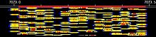 Spectrogram (waterfall display) of an Olivia 16/500 signal centered on 7073.25KHz
Olivia MFSK is an amateur radioteletype protocol designed to work in difficult (low signal-to-noise ratio plus multipath propagation) conditions on shortwave bands. The signal can still be properly copied when it is buried 10 dB below the noise floor (i.e. when the amplitude of the noise is just over 3 times that of the signal). It is commonly used by amateur radio operators to reliably transmit ASCII characters over noisy channels using the high frequency (3-30MHz) spectrum.
Olivia modes are commonly referred to as Olivia X / Y Where X refers to the number of different audio tones transmitted and Y refers to the bandwidth over which these signals are spread.
Contents
History
The protocol was developed at the end of 2003 by Pawel Jalocha. The first on-the-air tests were performed by two radio amateurs, Fred OH/DK4ZC and Les VK2DSG on the Europe-Australia path in the 20-meter amateur band. The tests proved that the protocol works well and can allow regular intercontinental radio contacts with as little as one watt RF power. Since 2005 Olivia has become a standard for digital data transfer under white noise, fading and multipath, flutter (polar path) and auroral conditions.
Voluntary channelization
Since Olivia signals can be decoded even when received signals are extremely weak, (signal to noise ratio of -14db),[1] signals strong enough to be decoded are sometimes below the noise floor and therefore impossible to search for manually. As a result amateur radio operators have voluntarily decided upon channelization for this mode. This channelization allows even imperceptibly weak signals to be properly tuned for reception and decoding. By common convention amateur stations initiate contacts utilizing either the 16/500 or 32/1000 modes and then switch to other modes to continue the conversation. The following table lists the common center frequencies used in the amateur radio bands.
Olivia Center Frequencies [2] Band 16/500 Frequencies (KHz) 32/1000 Frequencies (KHz) 160 Meters 1808.75, 1809.25, 1840.75, 1841.25 N/A 80 Meters 3577.75, 3583.25, 3522.75 3578.0, 3616.0, 3523.0, 3621.0 40 Meters 7026.25, 7043.25, 7073.25, 7076.75 N/A 30 Meters 10139.25, 10142.25, 10143.25 N/A 20 Meters 14076.4, 14075.4, 14078.4 14106.5, 14107.5, 14108.5 17 Meters 18103.4, 18104.4 N/A 15 Meters 21087.25, 21087.75, 21130.25 21153.5, 21154.5 12 Meters 24922.25 N/A 10 Meters 28076.75, 28077.25 N/A 6 Meters 50087.25, 50287.25, 50292.25 N/A 2 Meters 144136.25 N/A Tones and Bandwidth Combinations
Conversations using Olivia are by convention initiated using either Olivia 16/500 (16 tones over a 500hz bandwidth) or Olivia 32/1000 (32 tones over a 1000hz bandwidth).[3] Once communications have been established, the communicating parties mutually decide if another mode would better suit the current propagation conditions. The possible number of tones that can be chosen are 2, 4, 8, 16, 32, 64, 128, and 256 with higher numbers of tones giving more data redundancy but slower throughput and lower numbers of tones giving faster throughput at the cost of less redundancy. Available bandwidths for Olivia are 125hz, 256hz, 512hz, 500hz, 1000hz, and 2000hz with wider bandwidths giving faster throughput and narrower bandwidths giving slower throughput. The most commonly used combinations are 4/125, 8/250, 8/500, 16/500, 16/1000, and 32/1000.
The technical details
Being a digital protocol, Olivia transmits a stream of ASCII (7-bit) characters. The characters are sent in blocks of 5. Each block takes 2 seconds to transmit, thus the effective data rate is 2.5 character/second or 150 characters/minute. The most common transmission bandwidth is 1000 Hz and the baud rate is 31.25 MFSK tones/second. To accommodate for different conditions and for the purpose of experimentation the bandwidth and the baud rate can be changed.
The Olivia transmission system is constructed of two layers: the lower, modulation and forward error correcting (FEC) code layer is a classical multiple frequency-shift keying (MFSK) while the higher layer is a forward error correcting code based on Walsh functions.
Both layers are of similar nature: they constitute a "1-out-of-N" FEC code. For the first layer the orthogonal functions are (co)sine functions, with 32 different frequencies (tones). At a given time only one of those 32 tones is being sent. The demodulator measures the amplitudes of all the 32 possible tones (using a Fourier transform ) and (knowing that only one of those 32 could have been sent) picks up the tone with the highest amplitude. See the equations and graphs behind the MFSK layer here [broken link].
For the second FEC layer: every ASCII character is encoded as one of 64 possible Walsh functions (or vectors of a Hadamard matrix). The receiver again measures the amplitudes for all 64 vectors (here comes the Hadamard Transform) and chooses the greatest. See the algorithms and more details here [broken link].
For optimal performance the actual demodulators work with soft decisions and the final (hard) decision to decode a character is taken only at the second layer. Thus the first layer demodulator actually produces soft decisions for each of the 5 bits associated to an MFSK tone instead of simply picking up the highest tone to produce hard decisions for those 5 bits.
In order to avoid simple transmitted patterns (like a constant tone) and to minimize the chance for a false lock at the synchronizer the characters encoded into the Walsh function pass through a scrambler and interleaver. This stage simply shifts and XORs bits with predefined scrambling vectors and so it does not improve the performance where the white (uncorrelated) noise is concerned, but the resulting pattern gains certain distinct characteristics which are of great help to the synchronizer.
The receiver synchronizes automatically by searching through possible time and frequency offsets for a matching pattern. The frequency search range is normally +/- 100 Hz but can be as high as +/- 500 Hz if the user wishes so.
The MFSK layer
The default mode sends 32 tones within the 1000 Hz audio bandwidth and the tones are spaced by 1000 Hz/32 = 31.25 Hz. The tones are shaped to minimize the amount of energy sent outside the nominal bandwidth. The shape applied is plotted as the red trace on this graph[broken link]. The blue trace represents the more classical Hann window, which was used in the first version of the system.
The exact shape formula is:
- + 1.0000000000 + 1.1913785723cos(x) − 0.0793018558cos(2x) − 0.2171442026cos(3x) − 0.0014526076cos(4x)
where x ranges from – π to π.
 A plot of the window ("shape formula")
The coefficients represent the symbol shape in the frequency domain and were calculated by a minimization procedure which sought to make the smallest crosstalk and the smallest frequency spillover.
This graph [broken link] presents the 500 Hz MFSK tone (red trace) shaped according to the above formula. The blue trace is the envelope.
The tones are sent at 31.25 baud or every 32 milliseconds. The phase is not preserved from one tone to the next: instead a random shift of ±90 degrees is introduced in order not to transmit a pure tone when the same symbol is repeatedly sent. Because the symbols are smoothly shaped there is no need to keep the phase constant, which normally is the case when no (e.g. square) shaping is used.
The modulator uses the Gray code to encode 5-bit symbols into the tone numbers.
The waveform generator is based on the 8000 Hz sampling rate. The tones are spaced by 256 samples in time and the window that shapes them is 512 samples long. The demodulator is based on the FFT with the size of 512 points. The tone spacing in frequency is 8000 Hz/256 = 31.25 Hz and the demodulator FFT has the resolution of 8000 Hz/512 = 15.625 Hz thus half of the tone separation.
To adapt the system to different propagation conditions, the number of tones and the bandwidth can be changed and the time and frequency parameters are proportionally scaled. The number of tones can be 2, 4, 8, 16, 32, 64, 128 or 256. The bandwidth can be 125, 250, 500, 1000 or 2000 Hz.
The Walsh functions FEC layer
The modulation layer of the Olivia transmission system sends at a time one out of 32 tones (the default mode). Each tone constitutes thus a symbol that carries 5 bits of information. For the FEC code, 64 symbols are taken to form a block. Within each block one bit out of every symbol is taken and it forms a 64-bit vector coded as a Walsh function. Every 64-bit vector represents a 7-bit ASCII character, thus each block represents 5 ASCII characters.
This way, if one symbol (tone) becomes corrupted by the noise, only one bit of every 64-bit vector becomes corrupt, thus the transmission errors are spread uniformly across the characters within a block.
The two layers (MFSK+Walsh function) of the FEC code can be treated as a two dimensional code: the first dimension is formed along the frequency axis by the MFSK itself while the second dimension is formed along the time axis by the Walsh functions. The two dimensional arrangement was made with the idea in mind to solve such arranged FEC code with an iterative algorithm, however, no such algorithm was established to date.
The scrambling and simple bit interleaving is applied to make the generated symbol patterns appear more random and with minimal self-correlation. This avoids false locks at the receiver.
Bit interleaving: The Walsh function for the first character in a block is constructed from the 1st bit of the 1st symbol, the 2nd bit of the 2nd symbol, and so on. The 2nd Walsh function is constructed from the 2nd bit of the 1st symbol, the 3rd bit of the 2nd symbol, and so on.
Scrambling: The Walsh functions are scrambled with a pseudo-random sequence 0xE257E6D0291574EC. The Walsh function for the 1st character in a block is scrambled with the scrambling sequence, the 2nd Walsh function is scrambled with the sequence rotated right by 13 bits, the 3rd with the sequence rotated by 26 bits, and so on.
Samples
The listed audio files both are encoded with the message: "Welcome to Wikipedia, the free encyclopedia that anyone can edit."
External links
- Reference listing of common MFSK Olivia frequencies and formats
- GPL C++ source for Linux and Cygwin (web archive)
- Website containing technical information about the Olivia protocol
References
Amateur radio digital modes Frequency-shift keying (FSK) RTTY · AMTOR · PACTOR · CLOVER2000 · Packet radio (Bell 103 · Bell 202)
Multiple frequency-shift keying (MFSK) Olivia MFSK · JT65 · FSK441 · JT6M · WSPR
Phase-shift keying (PSK) Non-traditional digital modes Categories:- Quantized radio modulation modes
- Packet radio
- Amateur radio


Wikimedia Foundation. 2010.