- North American railroad signals
-
Main article: North American railway signaling
 Baltimore and Ohio Railroad Color Position Light bracket masts at Magnolia, West Virginia
North American railroad signals generally fall into the category of multi-headed electrically lit units displaying speed-based or weak route signaling.[1] Signals may be of the searchlight, color light, position light, or color position light types, each displaying a variety of aspects which inform the locomotive engineer of track conditions so that he or she may keep their train under control and able to stop short of any obstruction or dangerous condition.
There is no national standard or system for railroad signaling in North America. Individual railroad corporations are free to devise their own signaling systems as long as they uphold some basic regulated safety requirements. Due to the wave of mergers that have occurred since the 1960s it is not uncommon to see a single railroad operating many different types of signaling inherited from predecessor railroads. This variety can range from simple differences of hardware. to completely different rules and aspects. While there has been some recent standardization within railroads in terms of hardware and rules, diversity remains the norm.
This article will explain some of the aspects typically found in North American railroad signaling. For a more technical look at how signals actually work, see North American railway signaling.
Contents
Signaling aspect systems
There are two main types of signaling aspect systems found in North America, Speed Signaling and Weak Route Signaling.[2] Speed signaling transmits information regarding how fast the train must be going in the upcoming segment of track, weak route signaling transmits information related to the route a train will be taking through a junction and it is incumbent upon the engineer to govern the train's speed accordingly. Weak Route Signaling is applied with the term "Weak" because some speed signal aspects may be used in the system and also because exact route information is not typically conveyed, only the fact of a diverging or straight route, each having a predictable range of known speeds.
Typically railroads in the Eastern United States ran speed signaling, while railroads in the west used route signaling, with some mixing of systems in the Midwest and South. This was due to the lower train density in the west combined with generally simpler track layouts. Over time, the route signaling railroads have incorporated segments of speed signaling through merger and have also adopted more speed based aspects into their systems. Of the four major Class 1 railroads in the United States, CSX uses speed signaling, Union Pacific and BNSF use speed enhanced route signaling and Norfolk Southern uses a mix of speed and route signaling based on the original owner of the line. Commuter railroads and Amtrak all use speed signaling where they own or maintain the tracks they run on. Canadian railroads all use a strong system of speed signaling in Canada, but have some segments of route signaling on lines they have acquired in the United States.
Common signaling practices
Signal types
North American signals are commonly of three types.
- Absolute - Absolute signals are usually connected to an interlocking controlled by a block operator or train dispatcher. Their most restrictive aspect is "Stop" and trains cannot pass them at Stop unless they obtain special authority. Absolute signals will default to displaying Stop unless expressly cleared by a control authority.
- Automatic - Automatic signals are governed by logic connected through electrical track circuits which detect the presence of trains or obstructions automatically. Automatic signals are permissive with their most restrictive aspect being one of the "Restricted Proceed" variety. Trains can pass an automatic signal displaying "Restricted Proceed" without any outside permission. Automatic signals are typically recognized by having an attached number plate and in older practice, having multiple signal heads offset from each other on the mast.
- Semi-Automatic - Semi-Automatic signals are those that typically act as an automatic signal, but can be set to display an absolute "Stop" aspect. Semi-Automatic signals do not have a number plate, but can display an explicit "Restricted Proceed"-type signal.
Other types of signals can include Train Order signals, manual block signals or signals governing special safety appliances such as slide fences, non-interlocked sidings, road crossings, etc. These are much less common than the three standard types.
Layout
 Stacked searchlight dwarf at Springfield, Massachusetts
North American signals generally follow a common layout. A high signal consists of one to three heads mounted roughly in a vertical stack, each head capable of displaying one to four different aspects. Automatic signals are identified with a number plate whereas absolute signals are not. The signal's aspect is based on a combination of the aspects each individual head displays. Where a signal has multiple heads, aspects are read from top to bottom and are described as "X over Y over Z."
Dwarf signals are smaller signals used in low speed or restricted clearance areas. Most signaling aspect systems have a parallel set of aspects for use with dwarf signals that differ from aspects used in high signals. Dwarf signals may have multiple heads just like a high signal, but sometimes dwarf signals use so-called "virtual heads" to save on space and cost. This is where a dwarf signal displays multiple lamps on what would ordinarily be a single signal head creating the effect of multiple signal heads. For example, a stack of dwarf lamps in the order Yellow/Red/Green can display plain Yellow, Red and Green as well as Yellow over Green and Red over Green.
Behind the signal head is placed a dark backing or target, which helps improve signal visibility in bright ambient lighting. Target designs vary, but are usually round or oval, depending on the layout of the signal lamps. For each type of signal there are usually a range of target dimensions that can be chosen by the individual railroad company. As dwarf signals are not designed to be seen from long distances, they are not generally equipped with targets.
Mounting
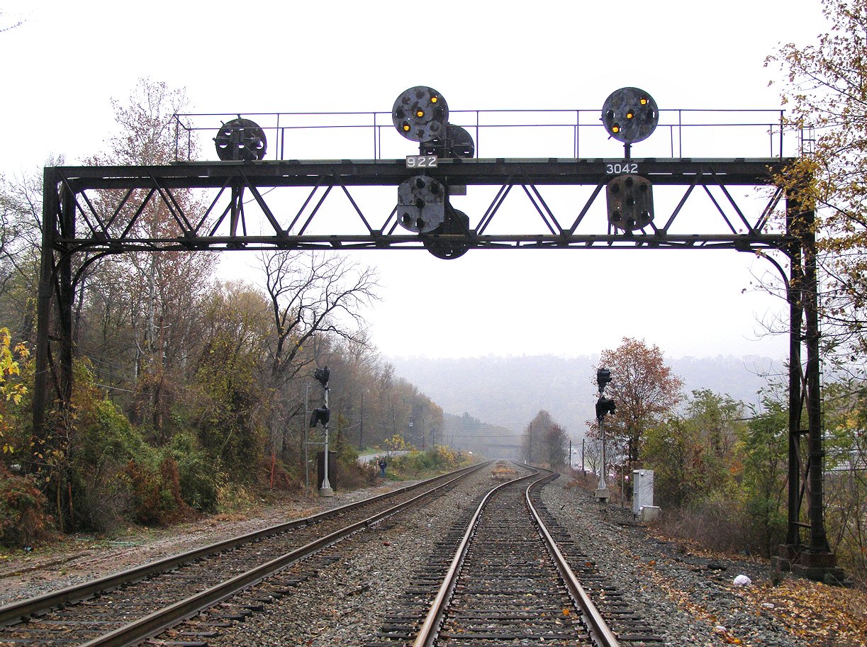
 Pennsylvania Railroad Position Light signal bridge with replacement mast signals in background. Steam locomotive design forced placement of signals to right of the track. Current diesel engine design allows ambidextrous placement.
Signals are most commonly mounted on trackside masts about 12 feet (3.7 m) to 15 feet (4.6 m) high to put them in the eyeline of the engineer. Signals can also be mounted on signal bridges or cantilever masts spanning multiple tracks. Signal bridges and masts typically provide at least 20 feet (6.1 m) of clearance over the top of the rail. Bracket masts are arranged with multiple signals are mounted on the same masts governing two adjacent tracks. Bracket masts tend to be the tallest type of signal to allow the train crew to see the signal over a train on the intervening track. Signals in electrified territory may be mounted on the catenary structure, and signals on bi-directional lines may be mounted back-to-back on the same mounting device.
Through the 1970s signals were commonly mounted to the right of the track they governed. This mounting was designed to allow the engineer to view the signal when driving a steam or diesel locomotive with a long nose that restricted the view to the left. Where bi-directional running was implemented, signals needed to be mounted above the track or on bracket masts to allow this right hand placement. As locomotive design changed to allow good visibility on both sides of the track railroads shifted to bi-directional mast type signals, using signal bridges only in special situations involving multiple tracks or restricted views.
Dwarf signals are typically mounted on the ground in areas of low speed movements of restricted clearances. Dwarf signals may be sometimes mounted higher up on a small mast or other structure for improved visibility. These can be known as "high dwarfs" or "stick signals," but a tall mounting does not change the lower speed aspects of the dwarf signal.
Signal colors and lamps
Electric signal lamps are typically low power (35 watt) incandescent lamps running off of low voltage DC current or, more recently, high intensity LED arrays. Incandescent signals use a doublet lens combination to directionally focus their small power out over a long range (3,500 feet in daylight.) New LED signals may either use an unfocused array or act as a drop-in replacement behind a traditional lens. U.S. signal lenses have a standard diameter of 8.375 inches (21.27 cm). North American signals use a standard set of colors, defined in October 1905, and which became common to other modes of transportation.[citation needed]
- Green - Used to indicate "clear" or proceed.
- Yellow - Used to warn the engineer of an impending stop or speed reduction for an occupied "block" ahead. Also used for low-speed movements.
- Red - Used to indicate a full stop or other restrictive condition, or used as a "placeholder" light.
- Blue - When on a signal doll arm indicates intervening track between signal and track signal applies to.
- Purple - Obsolete. No longer used on "Derails" and declared illegal in 1952 as a dwarf signal "Stop" indication color (pursuant to an Interstate Commerce Commission (ICC) ruling).
- Lunar White - Blue filtered light to eliminate all trace of yellow used to indicate a restricted proceed condition.
- lemon yellow - Used in position light systems as an all-purpose high visibility color, greatest fog penetration.
- (Plain) White - Plain incandescent white light. Used in dwarf position light signals with frosted lenses.
Individual signal heads may be set to flash a color to create a different signal aspect. Signals in the United States typically flash only one head at a time, while signals in Canada may flash two heads at a time.
Speeds
Signal rules and aspects make use of several pre-defined speeds. These speeds are also used in Weak Route type signaling.
- Normal Speed - The normal speed for the railroad line, also known as Maximum Authorized Speed (MAS).
- Limited Speed - A speed less than Normal Speed that was employed starting in the 1940s for use with higher speed turnouts (switches). This speed is defined by individual railroads and ranges anywhere from 40 miles per hour (64 km/h) to 60 miles per hour (97 km/h).
- Medium Speed - Original concept for a standard "reduced" speed normally set to 30 miles per hour (48 km/h). This is the typical speed for diverging movements through interlockings and is also the speed trains are limited to when approaching a Stop or Restricted Proceed-type signals.
- Slow Speed - 15 miles per hour (24 km/h) while with in the limits of a interlocking and 20mph when not in the limits of a interlocking. This is used for trains negotiating complex trackwork at interlockings.
- Restricted Speed - Used for trains entering or operating in unsignaled territory or when entering an de-energized track circuit. Regulatory definition of no greater than 20 miles per hour (32 km/h) outside interlocking limits, 15 mph within interlocking limits. Trains operating at restricted speed must be able to stop within half vision short of any obstruction, and must look out for broken rails.
Fault tolerance
Signal aspects are designed to incorporate some degree of fault tolerance. Aspects are often designed so that a faulty or obscured lamp will cause the resulting aspect to be more restrictive than the intended one. Operating rules (GCOR, NORAC or CROR) require that dark or obscured signal heads be treated as displaying their most restrictive aspect (i.e. red), but fault-tolerant aspect design can help the engineer take a safer course of action before the failure of a signal becomes apparent. While not all aspects are fault-tolerant, the green lamp on the topmost head is only used by the least restrictive signal aspect, "Clear," so there is no case where a failure could accidentally display a clear signal.
Where an signal aspect incorporates a flashing lamp, the flashing lamp is always applied to less restrictive signals. This is to prevent a stuck flashing relay from accidentally upgrading the signal.
Some signaling logic incorporates "bulb out" (lamp failure) or other fault detection, to attempt to display the most restrictive aspect in case of a fault. However, this feature is not required nor universally adopted.
Signal types
Main article: Railway signalSearchlight signals
 Searchlight bracket mast on the Delaware and Hudson at Saratoga Springs, New York
By late 1916, the management of the Hall Signal Company was fully aware that its latest product, the ultimate semaphore mechanism Style "L" (the very last produced by any U.S. signal company), had already been rendered obsolete by the advent of the doublet lens combination for daytime color light signals. That dual lens device had been developed by Cornell University's Dr. William Churchill, while he was working at Corning Glass Works. He had recently finished developing color standards for railroad glassware, which Corning had patented on October 10, 1905.[citation needed] The doublet lens combination was fully patented by 1911.
The doublet lens system was first placed into service on the Milwaukee Road electrified western route during 1917, in the double-lamp Union Switch & Signal (US&S) Style "L" color light signal. These signals had two lamps, so arranged that if the front failed, the rear would give an indication, albeit at a significantly lower wattage. Reflectors were used with this signal, which caused numerous phantom indications due to the reflection from engine headlights. Shortly thereafter the reflectors were entirely eliminated creating in effect the US&S Style "R" color light signal.
Hall's response to this dire situation was to buy the 1918 filed patents from one Mr. Blake for his "Searchlight" signal. In reality, the searchlight signal was an updated and modernized variation of the old Hall enclosed disc signal. What Blake had done was to harness the standard railroad three position polarized vane relay, add a miniature spectacle and roundels, and couple that with a very efficient elliptical reflector and optical lens system. This revolutionary development, provided a signal with a visible indication of over a mile from the signal in broad daylight, when the signal was located on tangent track. The early color light signals were visible for only about half that distance (2,500 feet) while using about the same current consumption, then a major concern in "Primary Battery Territory." By 1925, the development of "High Transmission Colors" of railroad glassware by Churchill and Corning Glass improved this limited distance to an acceptably competitive 3,500 feet on tangent track.[citation needed]
When the new Hall Searchlight signals were introduced in 1920, the recorded response by many engineman was classic: "They took the old 'Hall Banjo Signal,' resurrected it from the grave and lighted it up!"[citation needed]
In the U.K., original electromechanical searchlight signals consisted of a low wattage incandescent bulb mounted behind a semaphore spectacle devoid of a blade behind a target.
Searchlight signals became popular because of low maintenance, high visibility and the low power-consuming, 4 watt, 3 volt bulb worked well in "Primary Battery" territory. Vandalism of the searchlight signal relay and LED made the searchlight signal obsolete.
To overcome the issues of vulnerability of the moving parts of the searchlight design, new solid state, single-lensed signals have been developed. The first such product, marketed in 1968 as the "Unilens" by Safetran Systems, uses fiber optics to concentrate the output of up to four light sources behind a single lens. However, other than as low speed signals requiring only short range visibility, these have not been entirely successful and most are now being removed from mainline service after a relatively short worklife.[citation needed]
Searchlight signals are typically mounted with a large circular background, with one or two railroads preferring a small target, such as the New York Central beginning in the late 1950s.
Triangular color light signals
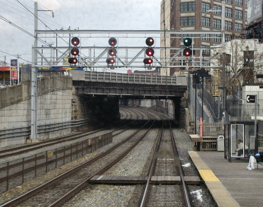
 Target style color light signals on SEPTA Main Line
Triangularly arranged color light signals consist of a cluster of three color lamp sockets in the middle of a large circular target. They were one of the first widely used type of high intensity color light signal, notably adopted by the New York Central and Seaboard Coast Line railroads, and later used exclusively by Conrail and New Jersey Transit.
The original General Railway Signal (GRS) Type "G" design consisted of a cast iron box containing three doublet lens units in a triangular arrangement. The US&S "TR" and "TP" models used three smaller connected single lamp housings with a common background. This design was later updated to a single unit akin to the GRS model. As modular color light signals have become widespread, target-type configurations have been typically offered alongside vertical type configurations. The triangular color light signal was especially useful in physically restricted and confined areas.[citation needed]
Vertical color light signals
 Non-modular 1, 2 and 3 lamp vertical color light heads on a mast mount
 "Darth Vader"-type modular color lights waiting to go into service
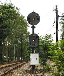 PRR high signal displaying "Approach Medium"
 New full B&O-style CPL signal at CARROLL interlocking, Baltimore, Maryland on CSX
 CPL dwarf signal at BAILEY interlocking on CSX, Baltimore
Vertical color light signals are the second major pattern of color light signals, and today represent the most popular form of signal in North America, supplanting the searchlight.[citation needed] These signals are not different from the triangular type color signal in function, but present a much altered visual appearance.
Continuing problems with reliable, long range light sources from a single, optical colored lens and a focused bulb restricted the first use of color light signals to short range daytime exterior applications, or tunnels and other underground or low speed complexes. The 1911 New York Penn Station project was one example of this type of color light signal, with an outer colored 8 3/8" optical lens, some of which are still in service as of 2011.
Development of the doublet lens by Churchill at Corning Glass Works allowed an electric light source to be more effectively than with previous daytime colorlight signal designs. There are two main types of cases: the single case, where two or more lamps were contained within a single cast housing, and the modular light, where each lamp was an independent unit capable of being arranged into a signal of arbitrary configuartion, including triangular. US&S has a popular single case type with its styles R/R-2, P-2/5 and N, while GRS offered their triangularly arranged Type G, with the Chicago Signal Company providing a similar version. Today's Safetrans Triangular is a copy of the GRS Type G but with vertically arranged double doors.
Signals like the model N/N-2 could also be mounted directly on the ground as a dwarf signal without a backing. The most notable user of this type of signal was the Chesapeake and Ohio, but units could be found on railroads all over the country.
Over time, due to its low cost and versatility, the modular color light signal became the standard in North America. The first modular system was the GRS Type "D", first marketed in 1922, and adopted by the Southern Railroad along with many others: D&RG, etc. The GRS units used a smaller "background" than the comparable US&S vertical possibly somewhat compromising long range visibility. Today the most popular type of new signal in North America is a modular design manufactured by Safetran, as it is the cheapest, with all of the four major Class 1 railroads installing it almost exclusively.[citation needed] Today, both GRS and Safetran market separate modular systems for high and dwarf signals, while US&S uses the single modular Style "R-2" design for high and Style N-2 for dwarfs.
Modular color lights allow for all the cost savings inherent in color lights, but also make it easier for railroads to stock signals and perform alterations to interlockings. Instead of having to order custom heads, new modules can be taken from stock to build new signals or modify existing heads.
With simple bracketry, even triangular colorlights may be built up with these standardized components.
Another ubiquitous feature of modern modular color light signals is the full-length sun shade which improves visibility in bright sunny conditions. This shade was first developed by the Union Pacific to prevent snow buildup on one shade from obscuring the signal lens above it. Due to the appearance of the shade, signals of this type have sophomorically been given the nickname Darth Vader by rail enthusiasts.
Position light signals
Position light signals are those which use rows of 5.375 inches (13.65 cm) diameter lamps to simulate the positions of an upper quadrant semaphore blade. Position lights were developed by A.H. Rudd, Superintendent of Signalling of the Pennsylvania Railroad (PRR). They were introduced in 1915 as a replacement for semaphore signals on the Main Line between Paoli and Philadelphia due to visibility problems caused by the new overhead electrification project. The original system used rows of four lights. The system was later reduced to use rows of three lamps, surrounding a common center. This reduced the "sail" effect of the inordinately large background of the four-light variant. The original installation made use of lamps positioned in front of a separate, tombstone shaped black sheet iron backing, but shortly thereafter, the lamps were fitted directly to the backing on a framework referred to as a "spider."[3]
Each position lamp unit is equipped with a 12 volt, 6 candlepower bulb mounted in front of a parabolic mirror that increases the relatively weak bulb's intensity. To avoid phantom indications the design makes use of a special inverted toric lens (i.e. a single clear Fresnel lens mounted step sides outwards) with a portion of the lens steps painted black. A conical amber tinted conical filter was chosen, as this color was determined to have the highest visibility under fog conditions based on empirical studies at the time.
A standard high position light consists of two heads, the bottom head can remain dark unless it is needed. In addition to the high position light signals the PRR developed a dwarf position light, as with many railroads, these dwarfs signals are also referred to as a "pot," a tradition carried over from the 19th century revolving "Pot Type Signal." Four plain white lamps are able to display four low-speed aspects each with two lamps. In 1930, close clearances of the Philadelphia Suburban Station complex spurred development of the pedestal-type position, which consisted of two position dwarf signals in a common cast backing.
PRR type position lights were used throughout the vast PRR system as well as the Long Island Rail Road (LIRR), a PRR subsidiary, and the Norfolk and Western, which was one-third-owned by the PRR. US&S was the sole supplier of classic position light equipment.
In 1954, the PRR experimented installing red lenses in the horizontal position of the upper head to help increase the recognizability of absolute Stop signals at Overbrook interlocking.[4] Under the Penn Central and later Conrail it became standard practice to add these red lenses to high position lights and even some pedestal signals. The Norfolk and Western modified its signals to use red and green lenses in the upper head Stop and Clear positions and yellow lenses everywhere else. In the 1980s Amtrak modified post of its former-PRR position lights to use the equivalent color light colors in all of the positions of both heads. Internally referred to as position color lights, these are not be confused with color position lights described below, which are entirely different structurally.
New PRR type position lights continued to be installed up until the 1980s on former Conrail systems. Today most of the old PRR position lights are slowly being replaced by modern color lights, but Amtrak and the LIRR continue to install new position lights, Amtrak's being of the colorized variety. US&S no longer manufactures position light equipment, but updated models from Safetran continue to be available.
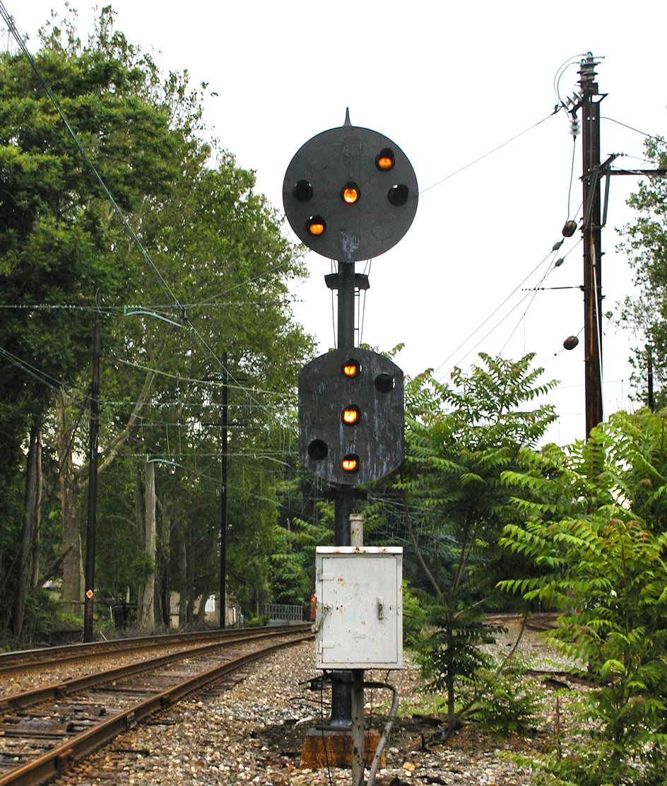
Color position light
The color position light (CPL) signal was develpoed by Frank Patenal, superintendent of signaling of the Baltimore and Ohio (B&O) railroad, in 1920. He also developed a proprietary signal aspect system to replace the earlier A.H. Rudd, ARA standard signaling system (PRR-based) then in use. The CPL system was unique in that it was a conceptually original design instead of being an update of an existing system. The CPL system incorporates several design principles that are otherwise unique to North American signaling. Use of the color red only in the case of an absolute stop or restricted speed situation is the most significant characteristic. The other 11 standard possible combinations do not display a red aspect.
The CPL consists of a central position target with up to four pairs of doublet lens units around the perimeter of the background disc. The lens units are spaced at 45-degree axes using the positions: green |, yellow /, red -- and a lunar white \ for restricting also being present in some installations. The main head is surrounded by up to 6 markers at the 12:00, 2:30, 4:30, 6:00, 8:30 and 10:30 o'clock positions. The function of the main head was block occupancy information with green representing two or more clear blocks, yellow one clear block and red/lunar white representing a restricting indication, meaning the engineman was permitted to enter his train into an occupied block. The orbitals provide speed information, 12 o'clock being Normal speed, 6 being Medium speed (Limited speed if flashing), 10 being Normal to Medium (Limited if flashing), 2 being Normal to Slow, 8 being Medium to Medium, 4 being Medium to Slow and no lit orbitals being Slow to Slow.
This CPL was first deployed on the Staten Island Railroad (a B&O subsidiary) in the 1920, and then deployed system-wide shortly thereafter. Later parts of the Chicago and Alton Railroad received CPLs when the B&O gained control of that line as well. In the 1980s both Amtrak's Chicago Union Station and Metra's Chicago Northwestern Station installed dwarf CPLs to replace earlier signals in those terminals.
As of 2008, CSX is slowly replacing all of the remaining CPLs on its system with contemporary vertical color light LED signals. The signals on the old Alton Railroad have also been almost entirely replaced as have many of the CPL dwarfs at the two Chicago terminals. The sole exception is the Staten Island Railroad, which recently upgraded its signaling system with new CPLs using modern Safetran position light equipment.
There are examples of these signals in the collections of enthusiasts that were manufactured by US&S, GRS and even the Hall Signal Company. The Hall Company's dwarf variant are the rarest and are most sought after.
Obsolete mechanical and electrical signals
Early mechanical signals
The first signals employed on an American railroad were a system of flags used on the Newcastle and Frenchtown Turnpike and Rail Road in the 1830s. The railroad then developed a more effective system consisting of wooden balls, painted white or black, and hoisted up or down on a rope and pulley system. The initial use of these signals was merely to indicate the on-time status of trains, rather than to control train movements. By the 1840s some railroads used ball signals to direct train movements.[5]:17-18
Disc signals
The disc signal was the first electrically-operated signal to be widely adopted by American railroads. Thomas Hall patented the disc signal in 1867.[6]:146-147
 Hall disc signal
A banjo-shaped wooden case housed a large iron wire hoop with red silk stretched and glued over it. The opposite end had a much smaller hoop in which was a very thin disc of colored glass was secured. This entire iron wire assembly was pivoted inside an electromagnet on an armature wound with fine copper wire. When the coil was energized, the wire hoops were moved away from the large glass opening in the front of the wooden "banjo" case exposing its white painted insides. The colored glass disc at the same time moving away from a clear primitive Fresnel lens at the top of the case which was backed up on the rear side of the case with a kerosene lamp.[7]:271 The disc signal was first placed into service in 1870 on the New York and New Haven Railroad at Stamford, Connecticut, using a track treadle device to activate it as the revolutionary track circuit was still some years away from invention at that time.[8]
The Hall Signal Company installed the disc signals as part of automatic block signal systems utilizing line wire circuits running on poles alongside the tracks connecting the track treadle devices. One of the earliest such system was installed in 1871 on the Eastern Railroad (later the Boston & Maine).[9]:18 About 1500 disc signals were operational by 1896.[10]:80
Semaphore signals
Main article: Railway semaphore signal Semaphore on ATSF Railway in 1943
Semaphore signals were first developed in England in 1841.[6]:169 Some U.S. railroads began to install them in the early 1860s, and semaphores gradually displaced other types of signals. US&S introduced an electro-pneumatic design in 1881. This was more reliable than earlier, purely mechanical versions, and more railroads began to use them. At that time, however, they were considerably more expensive than Hall disc signals.[6]:171
By the end of the 19th century, particularly as trains became longer and faster, and railroad lines grew more congested, the banjo signal was considered to have a single and terminal flaw: visibility. The internal disc was difficult to see in foggy weather and at night.[5]:39 Earlier types of electro-pneumatic semaphores made by US&S had seen some limited application by 1880 as automatic block signals. The need to maintain air pressure in the long pneumatic lines eventually led the railroads to discontinue their widespread use as automatic block signals. These types did however see long service in interlocking plants. Early semaphores also had limited range with manual wire operation and poor reliability in bad weather.[6]:149, 170-171 Thus some railroads continued to use disc signals where between manual block station automatic block signal operation was needed.
By the early 1890s more railroads began installing electric motor-operated semaphore signals, which were visible during the day and under inclement weather conditions for thousands of feet. In 1893 the high voltage, electric motor automatic block signal semaphore made its debut. By 1898, the US&S Style "B" semaphore, the first successful low voltage, entirely enclosed mechanism electric motor semaphore appeared. It was revolutionary, improving on all earlier semaphore designs, with the last such example being taken out of service as recently as 2007.[citation needed]
The motor-controlled North American semaphores used since the advent of the track circuit block system provided a form of automation sought after by the railroads to reduce labor costs. Dwarf signals were worked mechanically to give restricting-type signals which did not rely on track circuits as did mast type signals at interlockings, but motorized dwarfs were more common after the development of the Model 2A signal in 1908. As early as 1915, the cost associated with semaphore maintenance, as well as visibility issues, spurred railroads to replace them with daytime color light and position light signals.
Semaphore signals have almost been completely replaced by light signals in North America, but they contain several important design elements. The overwhelming majority of semaphore type signals used in North America, and the only type surviving in service as of 2008 are of the three position, upper quadrant variety. Those of the lower quadrant variety would typically have two positions, but three lenses, two being of the more restrictive type. This was to reduce the chance of a malfunction or snowfall causing the signal to drop to its less restrictive position.
As of 2011, several active semaphores exist on a few segments of one mainline railroad in the west.
Common signal rule classes
Most North American railroads have between 10 to 20 separate signal rules, each which are often represented by multiple aspects. However, all of these complicated rules revolve around the simple premise of informing the locomotive engineers how they are to operate their train in the present location, and what they are to expect at the next signal location.[11] From here the large set of rules and aspects can be broken down into a small number of classes which are common to all North American signaling systems.
- Automatic Block - Block aspects convey basic track occupancy information and advise the engineer (operator) which of the basic signal rules (common to all railroads) he/she is to follow in the operation of his/her train at any point on the railway line. These include Clear, Advance Approach and Approach which instruct the engineer to "expect no stop", "expect stop at second signal" and "expect stop at next signal" respectively. Advance approach is only used in situation with short signal blocks to ensure trains have enough stopping distance. These are the most common signal aspects in North America and are the only aspects most automatic block signals need to display.
- Approach at Speed - When a train needs to be told to slow down due to dynamic conditions an "Approach Speed" aspect is used. These inform the engineer to slow to a prescribed speed by the next signal. The most common reason for this is that the train is to take a diverging, or non-Normal speed route at the next interlocking. Signals of this type include Approach Medium, Approach Limited, Approach Slow and Approach Diverging. These signals are typically displayed on the distant signal to an interlocking, but can sometimes be used with short signal blocks in place of Advance Approach.
- Diverge to Clear - This class appears only on absolute signals and informs the engineer that the train will be taking a diverging route and need not expect a stop at the next signal. In speed signaling the engineer is informed of the speed the train needs to take the route at, in weak route signaling the engineer is just informed of a diverging route. Signals in this class include Medium Clear, Slow Clear, Limited Clear and Diverging Clear.
- Diverge to Stop - Same as above only the train can expect to stop at the signal after the interlocking. These signals include Medium Approach, Slow Approach and Diverging Approach.
- Combination Signals - These combine functions of a "Diverge to" signal with an "Approach Speed" signal and occur in areas of complex trackwork where there are no intermediate signals between one interlocking and the next. In the United States only a few combination signals like Medium Approach Medium, Medium Approach Slow and Diverging Approach Medium/Slow are ever found in rulebooks and not frequently used in practice. The Canadian standard rulebook contains signal rules and aspects for every possible combination.[12]
- Restricted Speed Signal - This class of signals is displayed for trains moving into a block where a track circuit has been de-energized or does not exist. A "shunted" track circuit indicates a either the block is occupied by another train or railcar, or there is a problem such as a broken rail or flooded track. Where a track is not protected by track circuits that track must be presumed to be occupied. As the name implies this signal requires trains to move at Restricted speed, specifically with the ability to stop short of an obstruction. Restricted speed signals take many forms including Restricted and Restricted Proceed where trains must simply pass the signal at restricted speed and also Stop and Proceed, where a train must come to a complete stop before proceeding at restricted speed. Stop and Proceed has fallen out of favor with most freight railroads due to the fuel and time savings of allowing the trains to not come to a complete stop. This aspect class can be displayed on almost all railroads in North America.
- Stop Signal - Stop signals are displayed on Absolute signals, in fact the ability to display an absolute Stop is part of that signal type's definition. Stop is the most important signal as passing a signal at Stop presents a serious risk of accident. Engineers committing a Stop signal violation automatically have their Federal certification suspended and are frequently fired. Stop signals can only be passed upon special permission from a control authority.
- Cab Signaling Signals - Where cab signaling is employed without fixed trackside automatic signals, special signal aspects are required at absolute signals. These include some sort of absolute block "Super Clear" signal that allows passage to the next interlocking with a fixed signal and also the "Cab Speed" signal that informs the engineer to proceed under direction of cab signals.
Distant (approach) signals
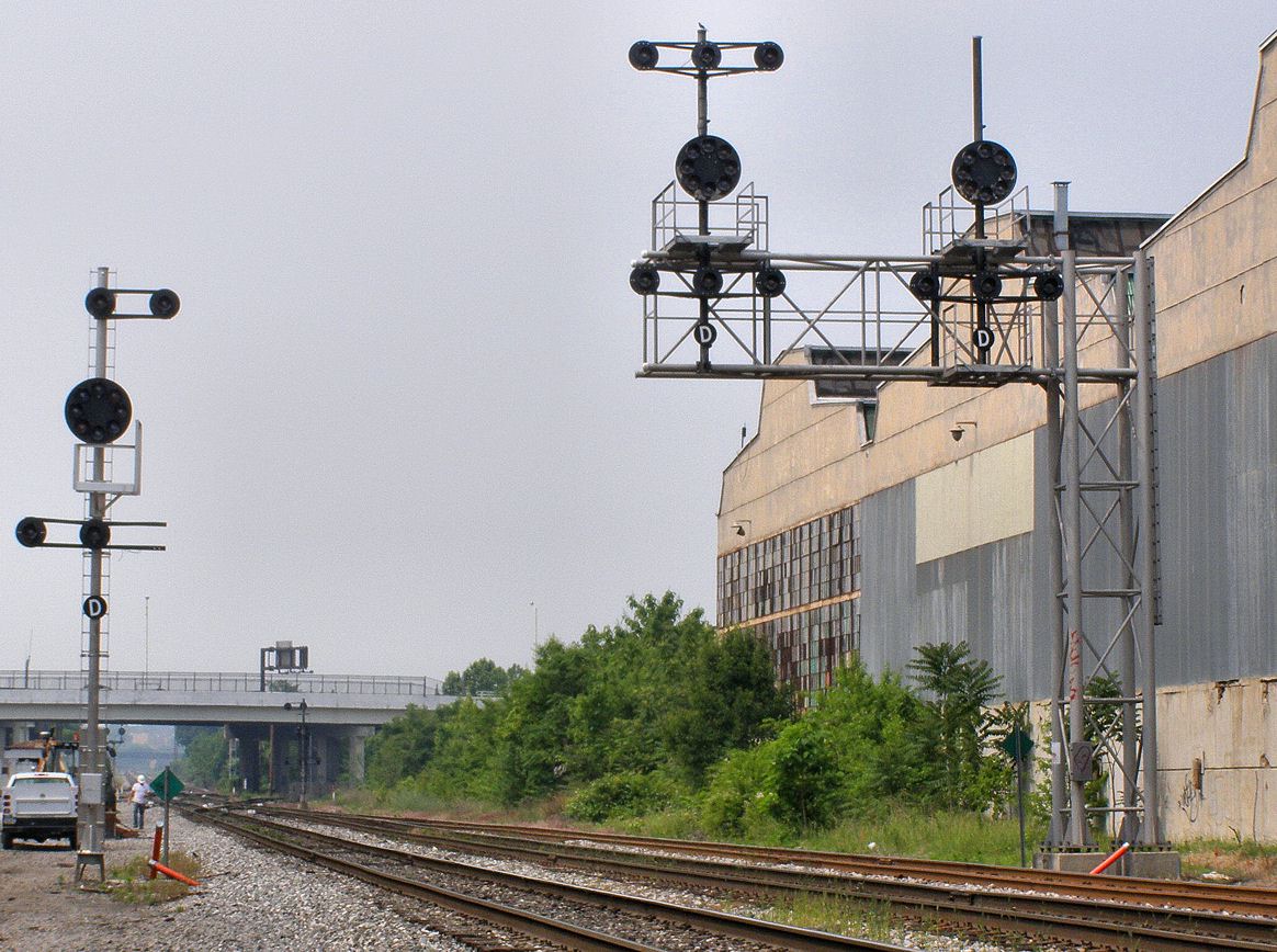
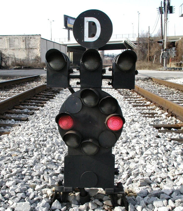
 A pair of distant signals on the NJT RiverLINE light rail. Note the 'D' boards placed in accordance with the NORAC "Delay in Block Rule."
A distant signal can either be an automatic signal before an interlocking, or the interlocking signal itself when interlockings are back to back. Distant signals typically display more aspects than a typical block or interlocking signal to warn trains of diverging movements at the next interlocking however this is not always the case if there are no diverging paths available.
Distant signals are often referred to as Approach Signals as the signal block before the interlocking is known as the approach block. When a train enters the approach block any route lined up at the interlocking will become locked in place until a timer is run to prevent routeing a conflicting movement without giving the approaching train adequate time to come to a stop.
In the aftermath of the 1996 Silver Spring Collision the Federal Railroad Administration amended its regulations for push-pull train operation to prevent locomotive engineers from forgetting that they were approaching a stop signal after making a station stop. The resulting "Delay in Block Rule" required that all distant signals in territory where push-pull trains operated in the absence of cab signals were to be marked with a "D" placard to remind engineers that they were bound by a 40 miles per hour (64 km/h) speed restriction between any station stop and the point where the home signal became visible.[13]
References
- ^ Bej, Mark D. "Significance of Signal Components (N. America)." Railway Signalling and Operations FAQ. 1997-04-16.
- ^ Bej, Mark D. "Learning the ('typical' US) Aspects." Railway Signalling and Operations FAQ. 1996-11-15.
- ^ Pennsylvania Railroad Technical & Historical Society, Philadelphia Chapter (2008). "PRR Position Light Signal System." Based on the original article by Edward Waytel. 2008-10-28.
- ^ Penn Central Railroad (1972). "Harrisburg Division-East; "Overbrook" Interlocking Station and Jeff & Valley Interlockings." Signal diagram. 1972-01-01.
- ^ a b Solomon, Brian (2003). Railroad Signaling. MBI Publishing. p. 55. ISBN 9780760313602.
- ^ a b c d Bianculli, Anthony J. (2003). "Volume 4. Bridges and Tunnels; Signals". Trains and Technology: The American Railroad in the Nineteenth Century. Cranbury, NJ: Associated University Presses. ISBN 0-87413-803-5. http://books.google.com/books?id=tbtdcXXnq5kC&lpg=PP1&pg=PP1#v=onepage&q&f=false.
- ^ King, Everett Edgar (1921). Railway Signaling. New York: McGraw-Hill. http://books.google.com/books?id=Qz8uAAAAYAAJ&pg=PR3#v=onepage&q&f=false.
- ^ New Haven Railroad Historical and Technical Association. "New Haven Railroad Historical Events (p.4)." Accessed 2011-10-12.
- ^ American Practice in Block Signaling. New York: Railroad Gazette. 1891. http://books.google.com/books?id=Q2w5AAAAMAAJ&pg=PP5#v=onepage&f=false.
- ^ Elliott, W. H. (1896). Block and Interlocking Signals. New York: Locomotive Engineering. http://books.google.com/books?id=kCffAq2KLp0C&pg=PP1#v=onepage&q&f=false.
- ^ Bej, Mark D. "RR Signal Aspect Speed Table (N. America)." Railway Signalling and Operations FAQ. 1997-03-31.
- ^ http://www.trainweb.org/railwayop/Signals2/signal2a.html[dead link]
- ^ U.S. Federal Railroad Administration (FRA), Washington, DC.
- Emergency Order No. 20, Notice No. 1 (1996-02-20). "Commuter and Intercity Passenger Railroads, Including Public Authorities Providing Passenger Service, and Affected Freight Railroads Emergency; Order Requiring Enhanced Operating Rules and Plans for Ensuring the Safety of Passengers Occupying the Leading Car of a Train."
- Emergency Order No. 20, Notice No. 2 (1996-03-05). "Commuter and Intercity Passenger Railroads, Including Public Authorities Providing Passenger Service, and Affected Freight Railroads; Clarification of Emergency Order Requiring Enhanced Operating Rules and Plans for Ensuring the Safety of Passengers Occupying the Leading Car of a Train With Appropriate Amendments." Federal Register, 61 FR 8703-06.
- Armstrong, John (1957). "All About Signals." Two-article series. Trains Magazine, June and July 1957.
- "Canadian Railway Operating Rules - CROR Signal Aspects." 2010-02-01.
- Pennsylvania Railroad (1964). "Rules for conducting transportation." 1964-08-25.
- Pennsylvania Railroad (1968). "Rules for conducting transportation." 1968-04-28
Categories:- Rail transport in North America
- Railway signaling in the United States
- Railway signaling in Canada
- Railway signaling in Mexico


Wikimedia Foundation. 2010.