- Faraday's law of induction
-
For the relationship between a time-varying magnetic field and an induced electric field, see Maxwell's equations.
Electromagnetism 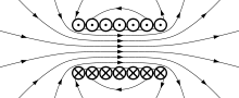
Electricity · Magnetism Lorentz force law · emf · Electromagnetic induction · Faraday’s law · Lenz's law · Displacement current · Maxwell's equations · EM field · Electromagnetic radiation · Liénard–Wiechert potential · Maxwell tensor · Eddy currentFaraday's law of induction dates from the 1830s, and is a basic law of electromagnetism relating to the operating principles of transformers, inductors, and many types of electrical motors and generators.[1] Faraday's law is applicable to a closed circuit made of thin wire and states that:
The induced electromotive force (EMF) in any closed circuit is equal to the time rate of change of the magnetic flux through the circuit.[1]
Or alternatively:
The EMF generated is proportional to the rate of change of the magnetic flux.
The law strictly holds only when the closed circuit is an infinitely-thin wire;[2] for example, a spinning homopolar generator has a constant magnetically-induced EMF, but its magnetic flux does not rise perpetually higher and higher, as would be implied by a naive interpretation of the statements above.[2]
EMF is defined as the energy available per unit charge that travels once around the wire loop (the unit of EMF is the volt).[2][3][4][5] Equivalently, it is the voltage that would be measured by cutting the wire to create an open circuit, and attaching a voltmeter to the leads. According to the Lorentz force law, the EMF on a wire loop is:
Faraday's law of induction is closely related to the Maxwell-Faraday equation:[2][3]
where:
 denotes curl
- E is the electric field
- B is the magnetic flux density.
The Maxwell-Faraday equation is one of the four Maxwell's equations, and therefore plays a fundamental role in the theory of classical electromagnetism.
History
Electromagnetic induction was discovered independently by Michael Faraday and Joseph Henry in 1831; however, Faraday was the first to publish the results of his experiments.[6][7]
 A diagram of Faraday's iron ring apparatus. Change in the magnetic flux of the left coil induces a current in the right coil.[8]
 Faraday's disk (see homopolar generator)
In Faraday's first experimental demonstration of electromagnetic induction (August 29, 1831[9]), he wrapped two wires around opposite sides of an iron torus (an arrangement similar to a modern transformer). Based on his assessment of recently-discovered properties of electromagnets, he expected that when current started to flow in one wire, a sort of wave would travel through the ring and cause some electrical effect on the opposite side. He plugged one wire into a galvanometer, and watched it as he connected the other wire to a battery. Indeed, he saw a transient current (which he called a "wave of electricity") when he connected the wire to the battery, and another when he disconnected it.[10] This induction was due to the change in magnetic flux that occurred when the battery was connected and disconnected.[8] Within two months, Faraday had found several other manifestations of electromagnetic induction. For example, he saw transient currents when he quickly slid a bar magnet in and out of a coil of wires, and he generated a steady (DC) current by rotating a copper disk near a bar magnet with a sliding electrical lead ("Faraday's disk").[11]
Faraday explained electromagnetic induction using a concept he called lines of force. However, scientists at the time widely rejected his theoretical ideas, mainly because they were not formulated mathematically.[12] An exception was Maxwell, who used Faraday's ideas as the basis of his quantitative electromagnetic theory.[12][13][14] In Maxwell's papers, the time varying aspect of electromagnetic induction is expressed as a differential equation which Oliver Heaviside referred to as Faraday's law even though it is slightly different in form from the original version of Faraday's law, and does not describe motional EMF. Heaviside's version (see Maxwell-Faraday equation below) is the form recognized today in the group of equations known as Maxwell's equations.
Lenz's law, formulated by Heinrich Lenz in 1834, describes "flux through the circuit", and gives the direction of the induced electromotive force and current resulting from electromagnetic induction (elaborated upon in the examples below).
 Faraday's experiment showing induction between coils of wire: The liquid battery (right) provides a current which flows through the small coil (A), creating a magnetic field. When the coils are stationary, no current is induced. But when the small coil is moved in or out of the large coil (B), the magnetic flux through the large coil changes, inducing a current which is detected by the galvanometer (G).[15]
Faraday's law as two different phenomena
Some physicists have remarked that Faraday's law is a single equation describing two different phenomena: the motional EMF generated by a magnetic force on a moving wire (see Lorentz force), and the transformer EMF generated by an electric force due to a changing magnetic field (due to the Maxwell-Faraday equation). James Clerk Maxwell drew attention to this fact in his 1861 paper On Physical Lines of Force. In the latter half of part II of that paper, Maxwell gives a separate physical explanation for each of the two phenomena.[citation needed] A reference to these two aspects of electromagnetic induction is made in some modern textbooks.[16] As Richard Feynman states:[2]
So the "flux rule" that the emf in a circuit is equal to the rate of change of the magnetic flux through the circuit applies whether the flux changes because the field changes or because the circuit moves (or both).... Yet in our explanation of the rule we have used two completely distinct laws for the two cases –
 for "circuit moves" and
  for "field changes".
We know of no other place in physics where such a simple and accurate general principle requires for its real understanding an analysis in terms of two different phenomena.— Richard P. Feynman, The Feynman Lectures on Physics
Reflection on this apparent dichotomy was one of the principal paths that led Einstein to develop special relativity:
It is known that Maxwell's electrodynamics—as usually understood at the present time—when applied to moving bodies, leads to asymmetries which do not appear to be inherent in the phenomena. Take, for example, the reciprocal electrodynamic action of a magnet and a conductor. The observable phenomenon here depends only on the relative motion of the conductor and the magnet, whereas the customary view draws a sharp distinction between the two cases in which either the one or the other of these bodies is in motion. For if the magnet is in motion and the conductor at rest, there arises in the neighbourhood of the magnet an electric field with a certain definite energy, producing a current at the places where parts of the conductor are situated. But if the magnet is stationary and the conductor in motion, no electric field arises in the neighbourhood of the magnet. In the conductor, however, we find an electromotive force, to which in itself there is no corresponding energy, but which gives rise—assuming equality of relative motion in the two cases discussed—to electric currents of the same path and intensity as those produced by the electric forces in the former case.
Examples of this sort, together with unsuccessful attempts to discover any motion of the earth relative to the "light medium," suggest that the phenomena of electrodynamics as well as of mechanics possess no properties corresponding to the idea of absolute rest.— Albert Einstein, On the Electrodynamics of Moving Bodies[17]
Flux through a surface and EMF around a loop
 The wire loop (red) forms the boundary of a surface Σ (blue). The black arrows denote any vector field F(r, t) defined throughout space; in the case of Faraday's law, the relevant vector field is the magnetic flux density B, and it is integrated over the blue surface. The red arrow represents the fact that the wire loop may be moving and/or deforming.
 The definition of surface integral relies on splitting the surface Σ into small surface elements. Each element is associated with a vector dA of magnitude equal to the area of the element and with direction normal to the element and pointing outward.
Faraday's law of induction makes use of the magnetic flux ΦB through a hypothetical surface Σ whose boundary is a wire loop. Since the wire loop may be moving, we write Σ(t) for the surface. The magnetic flux is defined by a surface integral:
where dA is an element of surface area of the moving surface Σ(t), B is the magnetic field, and B·dA is a vector dot product. In more visual terms, the magnetic flux through the wire loop is proportional to the number of magnetic flux lines that pass through the loop.
When the flux changes—because B changes, or because the wire loop is moved or deformed, or both—Faraday's law of induction says that the wire loop acquires an EMF
 , defined as the energy available per unit charge that travels once around the wire loop (the unit of EMF is the volt). The EMF is given by the rate of change of the magnetic flux:
where
 is the magnitude of the electromotive force (EMF) in volts and ΦB is the magnetic flux in webers. The direction of the electromotive force is given by Lenz's law.
For a tightly-wound coil of wire, composed of N identical loops, each with the same ΦB, Faraday's law of induction states that
where N is the number of turns of wire and ΦB is the magnetic flux in webers through a single loop.
The Maxwell-Faraday equation
 An illustration of Kelvin-Stokes theorem with surface Σ its boundary ∂Σ and orientation n set by the right-hand rule.
A changing magnetic field creates an electric field; this phenomenon is described by the Maxwell-Faraday equation:[19]
where:
- denotes curl
- E is the electric field
- B is the magnetic flux density.
This equation appears in modern sets of Maxwell's equations and is often referred to as Faraday's law. It can also be written in an integral form by the Kelvin-Stokes theorem:[20]
where, as indicated in the figure:
- Σ is a surface bounded by the closed contour ∂Σ,
- E is the electric field,
- dℓ is an infinitesimal vector element of the contour ∂Σ,
- B is the magnetic field.
- dA is an infinitesimal vector element of surface Σ. If its direction is orthogonal to that surface patch, the magnitude is the area of an infinitesimal patch of surface.
Both dℓ and dA have a sign ambiguity; to get the correct sign, the right-hand rule is used, as explained in the article Kelvin-Stokes theorem. For a planar surface Σ, a positive path element dℓ of curve ∂Σ is defined by the right-hand rule as one that points with the fingers of the right hand when the thumb points in the direction of the normal n to the surface Σ.
The integral around ∂Σ is called a path integral or line integral. The surface integral at the right-hand side of the Maxwell-Faraday equation is the explicit expression for the magnetic flux ΦB through Σ.
Notice that a nonzero path integral for E is different from the behavior of the electric field generated by charges. A charge-generated E-field can be expressed as the gradient of a scalar field that is a solution to Poisson's equation, and has a zero path integral. See gradient theorem.
The integral equation is true for any path ∂Σ through space, and any surface Σ for which that path is a boundary.
If the path Σ is not changing in time, the equation can be rewritten:
Proof of Faraday's law
The four Maxwell's equations (including the Maxwell-Faraday equation), along with the Lorentz force law, are a sufficient foundation to derive everything in classical electromagnetism.[2][3] Therefore it is possible to "prove" Faraday's law starting with these equations.[21][22] Click "show" in the box below for an outline of this proof. (In an alternative approach, not shown here but equally valid, Faraday's law could be taken as the starting point and used to "prove" the Maxwell-Faraday equation and/or other laws.)
-
Outline of proof of Faraday's law from Maxwell's equations and the Lorentz force law. Consider the time-derivative of flux through a possibly-moving loop, with area Σ(t): The integral can change over time for two reasons: The integrand can change, or the integration region can change. These add linearly, therefore:
where t0 is any given fixed time. We will show that the first term on the right-hand side corresponds to transformer EMF, the second to motional EMF (see above). The first term on the right-hand side can be rewritten using the integral form of the Maxwell-Faraday equation:
 Area swept out by vector element dℓ of curve ∂Σ in time dt when moving with velocity v.
Next, we analyze the second term on the right-hand side:
This is the most difficult part of the proof; more details and alternate approaches can be found in references.[21][22][23] As the loop moves and/or deforms, it sweeps out a surface (see figure on right). The magnetic flux through this swept-out surface corresponds to the magnetic flux that is either entering or exiting the loop, and therefore this is the magnetic flux that contributes to the time-derivative. (This step implicitly uses Gauss's law for magnetism: Since the flux lines have no beginning or end, they can only get into the loop by getting cut through by the wire.) As a small part of the loop
 moves with velocity v for a short time dt, it sweeps out a vector area vector
  . Therefore, the change in magnetic flux through the loop here is
Therefore:
where v is the velocity of a point on the loop
 .
.Putting these together,
Meanwhile, EMF is defined as the energy available per unit charge that travels once around the wire loop. Therefore, by the Lorentz force law,
Combining these,

"Counterexamples" to Faraday's law
-

Faraday's disc electric generator. The disc rotates with angular rate ω, sweeping the conducting radius circularly in the static magnetic field B. The magnetic Lorentz force v × B drives the current along the conducting radius to the conducting rim, and from there the circuit completes through the lower brush and the axle supporting the disc. Thus, current is generated from mechanical motion.
-

A counterexample to Faraday's Law when over-broadly interpreted. A wire (solid red lines) connects to two touching metal plates (silver) to form a circuit. The whole system sits in a uniform magnetic field, normal to the page. If the word "circuit" is interpreted as "primary path of current flow" (marked in red), then the magnetic flux through the "circuit" changes dramatically as the plates are rotated, yet the EMF is almost zero, which contradicts Faraday's Law. After Feynman Lectures on Physics Vol. II page 17-3
Although Faraday's law is always true for loops of thin wire, it can give the wrong result if naively extrapolated to other contexts.[2] One example is the homopolar generator (above left): A spinning circular metal disc in a homogeneous magnetic field generates a DC (constant in time) EMF. In Faraday's law, EMF is the time-derivative of flux, so a DC EMF is only possible if the magnetic flux is getting uniformly larger and larger perpetually. But in the generator, the magnetic field is constant and the disc stays in the same position, so no magnetic fluxes are growing larger and larger. So this example cannot be analyzed directly with Faraday's law.
Another example, due to Feynman,[2] has a dramatic change in flux through a circuit, even though the EMF is arbitrarily small. See figure and caption above right.
In both these examples, the changes in the current path are different from the motion of the material making up the circuit. The electrons in a material tend to follow the motion of the atoms that make up the material, due to scattering in the bulk and work function confinement at the edges. Therefore, motional EMF is generated when a material's atoms are moving through a magnetic field, dragging the electrons with them, thus subjecting the electrons to the Lorentz force. In the homopolar generator, the material's atoms are moving, even though the overall geometry of the circuit is staying the same. In the second example, the material's atoms are almost stationary, even though the overall geometry of the circuit is changing dramatically. On the other hand, Faraday's law always holds for thin wires, because there the geometry of the circuit always changes in a direct relationship to the motion of the material's atoms.
Although Faraday's law does not apply to all situations, the Maxwell-Faraday equation and Lorentz force law are always correct and can always be used directly.[2]
Electrical generator
 Rectangular wire loop rotating at angular velocity ω in radially outward pointing magnetic field B of fixed magnitude. Current is collected by brushes attached to top and bottom discs, which have conducting rims. This is a simplified version of the drum generatorMain article: electrical generator
The EMF generated by Faraday's law of induction due to relative movement of a circuit and a magnetic field is the phenomenon underlying electrical generators. When a permanent magnet is moved relative to a conductor, or vice versa, an electromotive force is created. If the wire is connected through an electrical load, current will flow, and thus electrical energy is generated, converting the mechanical energy of motion to electrical energy. For example, the drum generator is based upon the figure to the right. A different implementation of this idea is the Faraday's disc, shown in simplified form on the right.
In the Faraday's disc example, the disc is rotated in a uniform magnetic field perpendicular to the disc, causing a current to flow in the radial arm due to the Lorentz force. It is interesting to understand how it arises that mechanical work is necessary to drive this current. When the generated current flows through the conducting rim, a magnetic field is generated by this current through Ampère's circuital law (labeled "induced B" in the figure). The rim thus becomes an electromagnet that resists rotation of the disc (an example of Lenz's law). On the far side of the figure, the return current flows from the rotating arm through the far side of the rim to the bottom brush. The B-field induced by this return current opposes the applied B-field, tending to decrease the flux through that side of the circuit, opposing the increase in flux due to rotation. On the near side of the figure, the return current flows from the rotating arm through the near side of the rim to the bottom brush. The induced B-field increases the flux on this side of the circuit, opposing the decrease in flux due to rotation. Thus, both sides of the circuit generate an emf opposing the rotation. The energy required to keep the disc moving, despite this reactive force, is exactly equal to the electrical energy generated (plus energy wasted due to friction, Joule heating, and other inefficiencies). This behavior is common to all generators converting mechanical energy to electrical energy.
Electrical motor
Main article: electrical motorAn electrical generator can be run "backwards" to become a motor. For example, with the Faraday disc, suppose a DC current is driven through the conducting radial arm by a voltage. Then by the Lorentz force law, this traveling charge experiences a force in the magnetic field B that will turn the disc in a direction given by Fleming's left hand rule. In the absence of irreversible effects, like friction or Joule heating, the disc turns at the rate necessary to make d ΦB / dt equal to the voltage driving the current.
Electrical transformer
Main article: transformerThe EMF predicted by Faraday's law is also responsible for electrical transformers. When the electric current in a loop of wire changes, the changing current creates a changing magnetic field. A second wire in reach of this magnetic field will experience this change in magnetic field as a change in its coupled magnetic flux, a d ΦB / d t. Therefore, an electromotive force is set up in the second loop called the induced EMF or transformer EMF. If the two ends of this loop are connected through an electrical load, current will flow.
Magnetic flow meter
Main article: magnetic flow meterFaraday's law is used for measuring the flow of electrically conductive liquids and slurries. Such instruments are called magnetic flow meters. The induced voltage ℇ generated in the magnetic field B due to a conductive liquid moving at velocity v is thus given by:
where ℓ is the distance between electrodes in the magnetic flow meter.
Parasitic induction and waste heating
All metal objects moving in relation to a static magnetic field will experience inductive power flow, as do all stationary metal objects in relation to a moving magnetic field. These power flows are occasionally undesirable, resulting in flowing electric current at very low voltage and heating of the metal.
There are a number of methods employed to control these undesirable inductive effects.
- Electromagnets in electric motors, generators, and transformers do not use solid metal, but instead use thin sheets of metal plate, called laminations. These thin plates reduce the parasitic eddy currents, as described below.
- Inductive coils in electronics typically use magnetic cores to minimize parasitic current flow. They are a mixture of metal powder plus a resin binder that can hold any shape. The binder prevents parasitic current flow through the powdered metal.
Electromagnet laminations
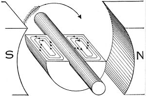
Eddy currents occur when a solid metallic mass is rotated in a magnetic field, because the outer portion of the metal cuts more lines of force than the inner portion, hence the induced electromotive force not being uniform, tends to set up currents between the points of greatest and least potential. Eddy currents consume a considerable amount of energy and often cause a harmful rise in temperature.[24]
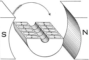
Only five laminations or plates are shown in this example, so as to show the subdivision of the eddy currents. In practical use, the number of laminations or punchings ranges from 40 to 66 per inch, and brings the eddy current loss down to about one percent. While the plates can be separated by insulation, the voltage is so low that the natural rust/oxide coating of the plates is enough to prevent current flow across the laminations.[24]
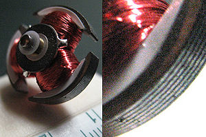
This is a rotor approximately 20mm in diameter from a DC motor used in a CD player. Note the laminations of the electromagnet pole pieces, used to limit parasitic inductive losses.
Parasitic induction within inductors
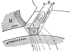
In this illustration, a solid copper bar inductor on a rotating armature is just passing under the tip of the pole piece N of the field magnet. Note the uneven distribution of the lines of force across the bar inductor. The magnetic field is more concentrated and thus stronger on the left edge of the copper bar (a,b) while the field is weaker on the right edge (c,d). Since the two edges of the bar move with the same velocity, this difference in field strength across the bar creates whorls or current eddies within the copper bar.[25]
This is one reason high voltage devices tend to be more efficient than low voltage devices. High voltage devices use many turns of small-gauge wire in motors, generators, and transformers. These many small turns of inductor wire in the electromagnet break up the eddy flows that can form within the large, thick inductors of low voltage, high current devices.
See also
References
- ^ a b Sadiku, M. N. O. (2007). Elements of Electromagnetics (fourth ed.). New York (USA)/Oxford (UK): Oxford University Press. p. 386. ISBN 0-19-530048-3. http://books.google.com/?id=w2ITHQAACAAJ&dq=isbn:0-19-530048-3.
- ^ a b c d e f g h i "The flux rule" is the terminology that Feynman uses to refer to the law relating magnetic flux to EMF. Richard Phillips Feynman, Leighton R B & Sands M L (2006). The Feynman Lectures on Physics. San Francisco: Pearson/Addison-Wesley. Vol. II, pp. 17-2. ISBN 0805390499. http://books.google.com/?id=zUt7AAAACAAJ&dq=intitle:Feynman+intitle:Lectures+intitle:on+intitle:Physics.
- ^ a b c Griffiths, David J. (1999). Introduction to Electrodynamics (Third ed.). Upper Saddle River NJ: Prentice Hall. pp. 301–303. ISBN 0-13-805326-X. http://www.amazon.com/gp/reader/013805326X/ref=sib_dp_pt/104-2951702-6987112#reader-link.
- ^ Tipler and Mosca, Physics for Scientists and Engineers, p795, google books link
- ^ Note that different textbooks may give different definitions. The set of equations used throughout the text was chosen to be compatible with the special relativity theory.
- ^ Ulaby, Fawwaz (2007). Fundamentals of applied electromagnetics (5th ed.). Pearson:Prentice Hall. p. 255. ISBN 0-13-241326-4. http://www.amazon.com/exec/obidos/tg/detail/-/0132413264/ref=ord_cart_shr?%5Fencoding=UTF8&m=ATVPDKIKX0DER&v=glance.
- ^ "Joseph Henry". Distinguished Members Gallery, National Academy of Sciences. http://www.nas.edu/history/members/henry.html. Retrieved 2006-11-30.
- ^ a b Giancoli, Douglas C. (1998). Physics: Principles with Applications (Fifth edition ed.). pp. 623–624.
- ^ Faraday, Michael; Day, P. (1999-02-01). The philosopher's tree: a selection of Michael Faraday's writings. CRC Press. p. 71. ISBN 9780750305709. http://books.google.com/books?id=ur6iKVmzYhcC&pg=PA71. Retrieved 28 August 2011.
- ^ Michael Faraday, by L. Pearce Williams, p. 182-3
- ^ Michael Faraday, by L. Pearce Williams, p. 191-5
- ^ a b Michael Faraday, by L. Pearce Williams, p. 510
- ^ Maxwell, James Clerk (1904), A Treatise on Electricity and Magnetism, Vol. II, Third Edition. Oxford University Press, pp. 178-9 and 189.
- ^ "Archives Biographies: Michael Faraday", The Institution of Engineering and Technology.
- ^ Poyser, Arthur William (1892), Magnetism and electricity: A manual for students in advanced classes. London and New York; Longmans, Green, & Co., p. 285, fig. 248. Retrieved 2009-08-06.
- ^ Griffiths, David J. (1999). Introduction to Electrodynamics (Third ed.). Upper Saddle River NJ: Prentice Hall. pp. 301–3. ISBN 0-13-805326-X. http://www.amazon.com/gp/reader/013805326X/ref=sib_dp_pt/104-2951702-6987112#reader-link. Note that the law relating flux to EMF, which this article calls "Faraday's law", is referred to in Griffiths' terminology as the "universal flux rule". Griffiths uses the term "Faraday's law" to refer to what article calls the "Maxwell-Faraday equation". So in fact, in the textbook, Griffiths' statement is about the "universal flux rule".
- ^ A. Einstein, On the Electrodynamics of Moving Bodies
- ^ Nave, Carl R.. "Faraday's Law". HyperPhysics. Georgia State University. http://hyperphysics.phy-astr.gsu.edu/hbase/electric/farlaw.html. Retrieved 29 August 2011.
- ^ The term Maxwell-Faraday equation frequently is replaced by Faraday's law of induction or even Faraday's law. These last two terms have multiple meanings, so Maxwell-Faraday equation is used here to avoid confusion.
- ^ Roger F Harrington (2003). Introduction to electromagnetic engineering. Mineola, NY: Dover Publications. p. 56. ISBN 0486432416. http://books.google.com/?id=ZlC2EV8zvX8C&pg=PA57&dq=%22faraday%27s+law+of+induction%22.
- ^ a b Davison, M. E. (1973). "A Simple Proof that the Lorentz Force, Law Implied Faraday's Law of Induction, when B is Time Independent". American Journal of Physics 41 (5): 713–711. doi:10.1119/1.1987339.
- ^ a b Basic Theoretical Physics: A Concise Overview by Krey and Owen, p155, google books link
- ^ K. Simonyi, Theoretische Elektrotechnik, 5th edition, VEB Deutscher Verlag der Wissenschaften, Berlin 1973, equation 20, page 47
- ^ a b Images and reference text are from the public domain book: Hawkins Electrical Guide, Volume 1, Chapter 19: Theory of the Armature, pp. 272-273, Copyright 1917 by Theo. Audel & Co., Printed in the United States
- ^ Images and reference text are from the public domain book: Hawkins Electrical Guide, Volume 1, Chapter 19: Theory of the Armature, pp. 270-271, Copyright 1917 by Theo. Audel & Co., Printed in the United States
Further reading
- Maxwell, James Clerk (1881), A treatise on electricity and magnetism, Vol. II, Chapter III, §530, p. 178. Oxford, UK: Clarendon Press. ISBN 0486606376.
External links
- A simple interactive Java tutorial on electromagnetic induction National High Magnetic Field Laboratory
- R. Vega Induction: Faraday's law and Lenz's law - Highly animated lecture
- Notes from Physics and Astronomy HyperPhysics at Georgia State University
- Faraday's Law for EMC Engineers
- Tankersley and Mosca: Introducing Faraday's law
Categories:- Electrodynamics
- Introductory physics
- Fundamental physics concepts
- Michael Faraday


Wikimedia Foundation. 2010.