- Microwave transmission
-
 The atmospheric attenuation of microwaves in dry air with a precipitable water vapor level of 0.001 mm. The downward spikes in the graph correspond to frequencies at which microwaves are absorbed more strongly, such as by oxygen molecules
Microwave transmission refers to the technology of transmitting information or power by the use of radio waves whose wavelengths are conveniently measured in small numbers of centimeters; these are called microwaves. This part of the radio spectrum ranges across frequencies of roughly 1.0 gigahertz (GHz) to 30 GHz. These correspond to wavelengths from 30 centimeters down to 1.0 cm.
Microwaves are widely used for point-to-point communications because their small wavelength allows conveniently-sized antennas to direct them in narrow beams, which can be pointed directly at the receiving antenna. This allows nearby microwave equipment to use the same frequencies without interfering with each other, as lower frequency radio waves do. Another advantage is that the high frequency of microwaves gives the microwave band a very large information-carrying capacity; the microwave band has a bandwidth 30 times that of all the rest of the radio spectrum below it. A disadvantage is that microwaves are limited to line of sight propagation; they cannot pass around hills or mountains as lower frequency radio waves can.
Microwave radio transmission is commonly used in point-to-point communication systems on the surface of the Earth, in satellite communications, and in deep space radio communications. Other parts of the microwave radio band are used for radars, radio navigation systems, sensor systems, and radio astronomy.
The next higher part of the radio electromagnetic spectrum, where the frequencies are above 30 GHz and below 100 GHz, are called "millimeter waves" because their wavelengths are conveniently measured in millimeters, and their wavelengths range from 10 mm down to 3.0 mm. Radio waves in this band are usually strongly attenuated by the Earthly atmosphere and particles contained in it, especially during wet weather. Also, in wide band of frequencies around 60 GHz, the radio waves are strongly attenuated by molecular oxygen in the atmosphere. The electronic technologies needed in the millimeter wave band are also much more difficult to utilize than those of the microwave band.
Contents
Properties
- Suitable over line-of-sight transmission links without obstacles
- Provides large useful bandwidth when compared to lower frequencies (HF, VHF, UHF)
- Affected by the refractive index (temperature, pressure and humidity) of the atmosphere, rain (see rain fade), snow and hail, sand storms, clouds, mist and fog, strongly depending on the frequency.
Uses
Wireless transmission of information
- One-way (e.g. television broadcasting) and two-way telecommunication using communications satellite
- Terrestrial microwave radio broadcasting relay links in telecommunications networks including e.g. backbone or backhaul carriers in cellular networks linking BTS-BSC and BSC-MSC.
 Military microwave set in Switzerland
Wireless transmission of power
- Proposed systems e.g. for connecting solar power collecting satellites to terrestrial power grids
Parabolic (microwave) antenna
Main article: Parabolic antennaTo direct microwaves in narrow beams for point-to-point communication links or radiolocation (radar, a parabolic antenna is usually used. This is an antenna that uses a parabolic reflector to direct the microwaves. To achieve narrow beamwidths, the reflector must be much larger than the wavelength of the radio waves. The relatively short wavelength of microwaves allows reasonably sized dishes to exhibit the desired highly directional response for both receiving and transmitting.
Microwave power transmission
Microwave power transmission (MPT) is the use of microwaves to transmit power through outer space or the atmosphere without the need for wires. It is a sub-type of the more general wireless energy transfer methods.
History
Following World War II, which saw the development of high-power microwave emitters known as cavity magnetrons, the idea of using microwaves to transmit power was researched. In 1964, William C. Brown demonstrated a miniature helicopter equipped with a combination antenna and rectifier device called a rectenna. The rectenna converted microwave power into electricity, allowing the helicopter to fly.[1] In principle, the rectenna is capable of very high conversion efficiencies - over 90% in optimal circumstances.
Most proposed MPT systems now usually include a phased array microwave transmitter. While these have lower efficiency levels they have the advantage of being electrically steered using no moving parts, and are easier to scale to the necessary levels that a practical MPT system requires.
Using microwave power transmission to deliver electricity to communities without having to build cable-based infrastructure is being studied at Grand Bassin on Reunion Island in the Indian Ocean.
 Microwave spying
During the Cold War, the US intelligence agencies, such as NSA, were reportedly able to intercept Soviet microwave messages using satellites such as Rhyolite.[2] Microwave also used in mobile communication.
Common safety concerns
The common reaction to microwave transmission is one of concern, as microwaves are generally perceived by the public as dangerous forms of radiation - stemming from the fact that they are used in microwave ovens. While high power microwaves can be painful and dangerous as in the United States Military's Active Denial System, MPT systems are generally proposed to have only low intensity at the rectenna.
Though this would be extremely safe as the power levels would be about equal to the leakage from a microwave oven, and only slightly more than a cell phone, the relatively diffuse microwave beam necessitates a large rectenna area for a significant amount of energy to be transmitted.
Research has involved exposing multiple generations of animals to microwave radiation of this or higher intensity, and no health issues have been found.[3]
Proposed uses
Main article: Solar power satelliteMPT is the most commonly proposed method for transferring energy to the surface of the Earth from solar power satellites or other in-orbit power sources. MPT is occasionally proposed for the power supply in [beam-powered propulsion] for orbital lift space ships. Even though lasers are more commonly proposed, their low efficiency in light generation and reception has led some designers to opt for microwave based systems.
Current status
Wireless Power Transmission (using microwaves) is well proven. Experiments in the tens of kilowatts have been performed at Goldstone in California in 1975[4][5][6] and more recently (1997) at Grand Bassin on Reunion Island.[7] In 2008 a long range transmission experiment successfully transmitted 20 watts 92 miles (148 km) from a mountain on Maui to the main island of Hawaii.[8]
Microwave radio relay
 Heinrich-Hertz-Turm in Germany
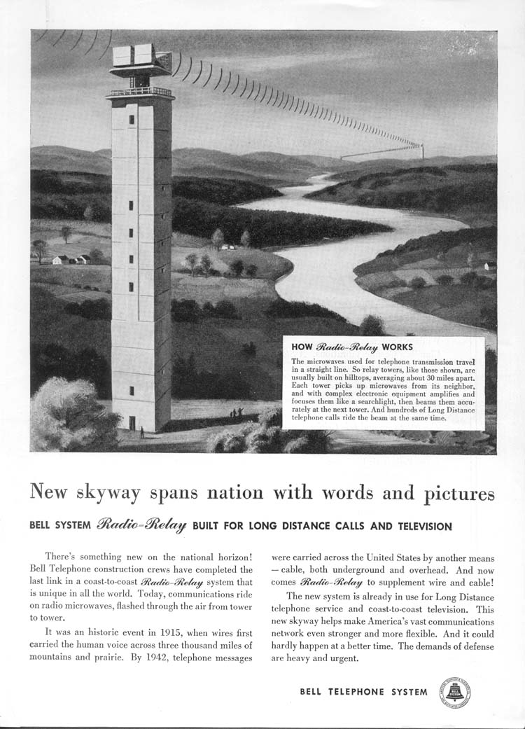
Microwave radio relay is a technology for transmitting digital and analog signals, such as long-distance telephone calls and the relay of television programs to transmitters, between two locations on a line of sight radio path. In microwave radio relay, radio waves are transmitted between the two locations with directional antennas, forming a fixed radio connection between the two points. Long daisy-chained series of such links form transcontinental telephone and/or television communication systems.
How microwave radio relay links are formed

Because a line of sight radio link is made, the radio frequencies used occupy only a narrow path between stations (with the exception of a certain radius of each station). Antennas used must have a high directive effect; these antennas are installed in elevated locations such as large radio towers in order to be able to transmit across long distances. Typical types of antenna used in radio relay link installations are parabolic reflectors, shell antennas and horn radiators, which have a diameter of up to 4 meters. Highly directive antennas permit an economical use of the available frequency spectrum, despite long transmission distances.
 Danish military radio relay node
Planning considerations
Because of the high frequencies used, a quasi-optical line of sight between the stations is generally required. Additionally, in order to form the line of sight connection between the two stations, the first Fresnel zone must be free from obstacles so the radio waves can propagate across a nearly uninterrupted path. Obstacles in the signal field cause unwanted attenuation, and are as a result only acceptable in exceptional cases. High mountain peak or ridge positions are often ideal: Europe's highest radio relay station, the Richtfunkstation Jungfraujoch, is situated atop the Jungfraujoch ridge at an altitude of 3,705 meters (12,156 ft) above sea level.
 Multiple antennas provide space diversity
Obstacles, the curvature of the Earth, the geography of the area and reception issues arising from the use of nearby land (such as in manufacturing and forestry) are important issues to consider when planning radio links. In the planning process, it is essential that "path profiles" are produced, which provide information about the terrain and Fresnel zones affecting the transmission path. The presence of a water surface, such as a lake or river, in the mid-path region also must be taken into consideration as it can result in a near-perfect reflection (even modulated by wave or tide motions), creating multipath distortion as the two received signals ("wanted" and "unwanted") swing in and out of phase. Multipath fades are usually deep only in a small spot and a narrow frequency band, so space and/or frequency diversity schemes would be applied to mitigate these effects.
The effects of atmospheric stratification cause the radio path to bend downward in a typical situation so a major distance is possible as the earth equivalent curvature increases from 6370 km to about 8500 km (a 4/3 equivalent radius effect). Rare events of temperature, humidity and pressure profile versus height, may produce large deviations and distortion of the propagation and affect transmission quality. High intensity rain and snow must also be considered as an impairment factor, especially at frequencies above 10 GHz. All previous factors, collectively known as path loss, make it necessary to compute suitable power margins, in order to maintain the link operative for a high percentage of time, like the standard 99.99% or 99.999% used in 'carrier class' services of most telecommunication operators. [[File:TV remote pickup Pier 88 jeh.JPG|thumb|left|Portable microwave rig for Electronic news gathering (ENG) for television news
Over-horizon microwave radio relay
In over-horizon, or tropospheric scatter, microwave radio relay, unlike a standard microwave radio relay link, the sending and receiving antennas do not use a line of sight transmission path. Instead, the stray signal transmission, known as "tropo - scatter" or simply "scatter," from the sent signal is picked up by the receiving station. Signal clarity obtained by this method depends on the weather and other factors, and as a result a high level of technical difficulty is involved in the creation of a reliable over horizon radio relay link. Over horizon radio relay links are therefore only used where standard radio relay links are unsuitable (for example, in providing a microwave link to an island).
Usage of microwave radio relay systems
During the 1950s the AT&T Communications system of microwave radio grew to carry the majority of US Long Distance telephone traffic, as well as intercontinental television network signals. The prototype was called TDX and was tested with a connection between New York City and Murray Hill, the location of Bell Laboratories in 1946. The TDX system was set up between New York and Boston in 1947. The TDX was improved to the TD2, which still used klystrons, and then later to the TD3 that used solid state electronics. The main motivation in 1946 to use microwave radio instead of cable was that a large capacity could be installed quickly and at less cost. It was expected at that time that the annual operating costs for microwave radio would be greater than for cable. There were two main reasons that a large capacity had to be introduced suddenly: Pent up demand for long distance telephone service, because of the hiatus during the war years, and the new medium of television, which needed more bandwidth than radio.
Similar systems were soon built in many countries, until the 1980s when the technology lost its share of fixed operation to newer technologies such as fiber-optic cable and optical radio relay links, both of which offer larger data capacities at lower cost per bit. Communication satellites, which are also microwave radio relays, better retained their market share, especially for television.
At the turn of the century, microwave radio relay systems are being used increasingly in portable radio applications. The technology is particularly suited to this application because of lower operating costs, a more efficient infrastructure, and provision of direct hardware access to the portable radio operator.
Listen to this article (info/dl)
 This audio file was created from a revision of Microwave transmission dated 2005-09-22, and does not reflect subsequent edits to the article. (Audio help)More spoken articles
Microwave link
A microwave link is a communications system that uses a beam of radio waves in the microwave frequency range to transmit video, audio, or data between two locations, which can be from just a few feet or meters to several miles or kilometers apart. Microwave links are commonly used by television broadcasters to transmit programmes across a country, for instance, or from an outside broadcast back to a studio.
Mobile units can be camera mounted, allowing cameras the freedom to move around without trailing cables. These are often seen on the touchlines of sports fields on Steadicam systems.
Properties of microwave links
- Involve line of sight (LOS) communication technology
- Affected greatly by environmental constraints, including rain fade
- Have very limited penetration capabilities through obstacles such as hills, buildings and trees
- Sensitive to high pollen count[citation needed]
- Signals can be degraded[citation needed]during Solar proton events [9]
Uses of microwave links
- In communications between satellites and base stations
- As backbone carriers for cellular systems
- In short range indoor communications
- Telecommunications, in linking remote and regional telephone exchanges to larger (main) exchanges without the need for copper/optical fibre lines.
See also
- Wireless energy transfer
- Fresnel zone
- Passive repeater
- Radio repeater
- Transmitter station
- Path loss
- British Telecom microwave network
- Trans-Canada Microwave
- Antenna array (electromagnetic)
References
- ^ EXPERIMENTAL AIRBORNE MICROWAVE SUPPORTED PLATFORM Descriptive Note : Final rept. Jun 64-Apr 65
- ^ James Bamford, The Shadow Factory, Doubleday, 2008, p 176
- ^ Environmental Effects - the SPS Microwave Beam
- ^ NASA Video, date/author unknown
- ^ Wireless Power Transmission for Solar Power Satellite (SPS) (Second Draft by N. Shinohara), Space Solar Power Workshop, Georgia Institute of Technology
- ^ Brown., W. C. (September 1984). "The History of Power Transmission by Radio Waves". Microwave Theory and Techniques, IEEE Transactions on (Volume: 32, Issue: 9 On page(s): 1230- 1242 + ISSN: 0018-9480). http://ieeexplore.ieee.org/xpl/freeabs_all.jsp?arnumber=1132833.
- ^ POINT-TO-POINT WIRELESS POWER TRANSPORTATION IN REUNION ISLAND 48th International Astronautical Congress, Turin, Italy, 6–10 October 1997 - IAF-97-R.4.08 J. D. Lan Sun Luk, A. Celeste, P. Romanacce, L. Chane Kuang Sang, J. C. Gatina - University of La Réunion - Faculty of Science and Technology.
- ^ http://www.wired.com/wiredscience/2008/09/visionary-beams/
- ^ Analyzing Microwave Spectra Collected by the Solar Radio Burst Locator
- Microwave Radio Transmission Design Guide, Trevor Manning, Artech House, 1999
External links
- RF / Microwave Design at Oxford University
- http://www.kurasc.kyoto-u.ac.jp/plasma-group/sps/history2-e.html
- William C. Brown's Distinguished Career
- AT&T's Microwave Radio-Relay Skyway introduced in 1951
- Bell System 1951 magazine ad for Microwave Radio-Relay systems.
- RCA vintage magazine ad for Microwave-Radio Relay equipment used for Western Union Telegraph Co.
- Digital Microwave Radio
- AT&T Long Lines Microwave Towers Remembered
- AT&T Long Lines
- Western Union Microwave Network History
- Trevor Manning's course 'Microwave Radio for Next Generation Networks' at Oxford University
- An article about how a microwave link is planned and how it works
- IEEE Global History Network Microwave Link Networks
Radio spectrum ELF
3 Hz/100 Mm
30 Hz/10 MmSLF
30 Hz/10 Mm
300 Hz/1 MmULF
300 Hz/1 Mm
3 kHz/100 kmVLF
3 kHz/100 km
30 kHz/10 kmLF
30 kHz/10 km
300 kHz/1 kmMF
300 kHz/1 km
3 MHz/100 mHF
3 MHz/100 m
30 MHz/10 mVHF
30 MHz/10 m
300 MHz/1 mUHF
300 MHz/1 m
3 GHz/100 mmSHF
3 GHz/100 mm
30 GHz/10 mmEHF
30 GHz/10 mm
300 GHz/1 mmTHF
300 GHz/1 mm
3 THz/0.1 mmElectromagnetic spectrum ← higher frequencies longer wavelengths →
Gamma rays · X-rays · Ultraviolet · Visible · Infrared · Terahertz radiation · Microwave · RadioVisible (optical) Microwaves Radio Wavelength types Telecommunications (general) History - Beacons
- Broadcasting
- Computer networks
- Drums
- Electrical telegraphy
- Fax
- Heliography
- Hydraulic telegraphs
- Internet
- Mass media
- Mobile phones
- Optical telegraphy
- Photophone
- Radio
- Radiotelephone
- Satellite communications
- Telegraphy
- Telephones
- Telephone patent controversies
- Television
- Undersea telegraph lines
- Videophones
Pioneers Mediums - Coaxial cable
- Free-space optical
- Landlines
- Optical fiber
- Radio waves
- Terrestrial microwave
Networks Geographic Telecommunications in Europe Sovereign
states- Albania
- Andorra
- Armenia
- Austria
- Azerbaijan
- Belarus
- Belgium
- Bosnia and Herzegovina
- Bulgaria
- Croatia
- Cyprus
- Czech Republic
- Denmark
- Estonia
- Finland
- France
- Georgia
- Germany
- Greece
- Hungary
- Iceland
- Ireland
- Italy
- Kazakhstan
- Latvia
- Liechtenstein
- Lithuania
- Luxembourg
- Macedonia
- Malta
- Moldova
- Monaco
- Montenegro
- Netherlands
- Norway
- Poland
- Portugal
- Romania
- Russia
- San Marino
- Serbia
- Slovakia
- Slovenia
- Spain
- Sweden
- Switzerland
- Turkey
- Ukraine
- United Kingdom
- (England
- Northern Ireland
- Scotland
- Wales)
States with limited
recognition- Abkhazia
- Kosovo
- Nagorno-Karabakh
- Northern Cyprus
- South Ossetia
- Transnistria
Dependencies
and other territories- Åland
- Faroe Islands
- Gibraltar
- Guernsey
- Jan Mayen
- Jersey
- Isle of Man
- Svalbard
Other entities Telecommunications in North America Sovereign states Dependencies and
other territories- Anguilla
- Aruba
- Bermuda
- Bonaire
- British Virgin Islands
- Cayman Islands
- Curaçao
- Greenland
- Guadeloupe
- Martinique
- Montserrat
- Navassa Island
- Puerto Rico
- Saint Barthélemy
- Saint Martin
- Saint Pierre and Miquelon
- Saba
- Sint Eustatius
- Sint Maarten
- Turks and Caicos Islands
- United States Virgin Islands
Telecommunications in South America Sovereign states Dependencies and
other territoriesTelecommunications in Oceania Sovereign states - Australia
- East Timor (Timor-Leste)
- Fiji
- Indonesia
- Kiribati
- Marshall Islands
- Federated States of Micronesia
- Nauru
- New Zealand
- Palau
- Papua New Guinea
- Samoa
- Solomon Islands
- Tonga
- Tuvalu
- Vanuatu
Dependencies and
other territories- American Samoa
- Christmas Island
- Cocos (Keeling) Islands
- Cook Islands
- Easter Island
- French Polynesia
- Guam
- Hawaii
- New Caledonia
- Niue
- Norfolk Island
- Northern Mariana Islands
- Pitcairn Islands
- Tokelau
- Wallis and Futuna
Telecommunications in Africa Sovereign
states- Algeria
- Angola
- Benin
- Botswana
- Burkina Faso
- Burundi
- Cameroon
- Cape Verde
- Central African Republic
- Chad
- Comoros
- Democratic Republic of the Congo
- Republic of the Congo
- Côte d'Ivoire (Ivory Coast)
- Djibouti
- Egypt
- Equatorial Guinea
- Eritrea
- Ethiopia
- Gabon
- The Gambia
- Ghana
- Guinea
- Guinea-Bissau
- Kenya
- Lesotho
- Liberia
- Libya
- Madagascar
- Malawi
- Mali
- Mauritania
- Mauritius
- Morocco
- Mozambique
- Namibia
- Niger
- Nigeria
- Rwanda
- São Tomé and Príncipe
- Senegal
- Seychelles
- Sierra Leone
- Somalia
- South Africa
- South Sudan
- Sudan
- Swaziland
- Tanzania
- Togo
- Tunisia
- Uganda
- Zambia
- Zimbabwe
States with limited
recognition- Sahrawi Arab Democratic Republic
- Somaliland
Dependencies and
other territories- Canary Islands / Ceuta / Melilla / Plazas de soberanía (Spain)
- Madeira (Portugal)
- Mayotte / Réunion (France)
- Saint Helena / Ascension Island / Tristan da Cunha (United Kingdom)
- Western Sahara
Telecommunications in Asia Sovereign
states- Afghanistan
- Armenia
- Azerbaijan
- Bahrain
- Bangladesh
- Bhutan
- Brunei
- Burma (Myanmar)
- Cambodia
- People's Republic of China
- Cyprus
- East Timor (Timor-Leste)
- Egypt
- Georgia
- India
- Indonesia
- Iran
- Iraq
- Israel
- Japan
- Jordan
- Kazakhstan
- North Korea
- South Korea
- Kuwait
- Kyrgyzstan
- Laos
- Lebanon
- Malaysia
- Maldives
- Mongolia
- Nepal
- Oman
- Pakistan
- Philippines
- Qatar
- Russia
- Saudi Arabia
- Singapore
- Sri Lanka
- Syria
- Tajikistan
- Thailand
- Turkey
- Turkmenistan
- United Arab Emirates
- Uzbekistan
- Vietnam
- Yemen
States with limited
recognition- Abkhazia
- Nagorno-Karabakh
- Northern Cyprus
- Palestine
- Republic of China (Taiwan)
- South Ossetia
Dependencies and
other territories- Christmas Island
- Cocos (Keeling) Islands
- Hong Kong
- Macau
Categories:- Microwave transmission
- Electromagnetic radiation
- Energy development
- Wireless energy transfer
- Microwave technology
- Wireless networking
- History of television
- Television terminology


Wikimedia Foundation. 2010.