- Diffraction-limited system
-
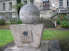 Memorial to Ernst Karl Abbe, who approximated the diffraction limit of a microscope as
 , where d is the resolvable feature size, λ is the wavelength of light, n is the index of refraction of the medium being imaged in, and θ (depicted as α in the inscription) is the half-angle subtended by the optical objective lens.
The resolution of an optical imaging system — a microscope, telescope, or camera — can be limited by factors such as imperfections in the lenses or misalignment. However, there is a fundamental maximum to the resolution of any optical system which is due to diffraction. An optical system with the ability to produce images with angular resolution as good as the instrument's theoretical limit is said to be diffraction limited.[1]
The resolution of a given instrument is proportional to the size of its objective, and inversely proportional to the wavelength of the light being observed. For telescopes with circular apertures, the size of the smallest feature in an image that is diffraction limited is the size of the Airy disc.
In astronomy, a diffraction-limited observation is one that is limited only by the optical power of the instrument used. However, most observations from Earth are seeing-limited due to atmospheric effects. Optical telescopes on the Earth work at a much lower resolution than the diffraction limit because of the distortion introduced by the passage of light through several kilometres of turbulent atmosphere. Some advanced observatories have recently started using adaptive optics technology, resulting in greater image resolution for faint targets, but it is still difficult to reach the diffraction limit using adaptive optics.
Radiotelescopes are frequently diffraction-limited, because the wavelengths they use (from millimeters to meters) are so long that the atmospheric distortion is negligible. Space-based telescopes (such as Hubble, or a number of non-optical telescopes) always work at their diffraction limit, if their design is free of optical aberration.
Contents
The Abbe diffraction limit for a microscope
The observation of sub-wavelength structures with microscopes is difficult because of the Abbe diffraction limit. Ernst Abbe found in 1873 that light with wavelength λ, traveling in a medium with refractive index n and converging to a spot with angle θ will make a spot with radius
The denominator nsin θ is called the numerical aperture (NA) and can reach about 1.4 in modern optics, hence the Abbe limit is roughly d=λ/2. With green light around 500nm the Abbe limit is 250nm which is large compared to most nanostructures or biological cells which have sizes on the order of 1μm and internal organelles which are much smaller. To increase the resolution, shorter wavelengths can be used such as UV and X-ray microscopes. These techniques offer better resolution but are expensive, suffer from lack of contrast in biological samples and may damage the sample.
Obtaining higher resolution
There are techniques for producing images that appear to have higher resolution than allowed by simple use of diffraction-limited optics.[3] Although these techniques improve some aspect of resolution, they generally come at an enormous increase in cost and complexity. Usually the technique is only appropriate for a small subset of imaging problems or are just badly named. An example is finding the center of sparsely-distributed blobs on a two-dimensional surface. Although the location is located exactly, the resolution is hardly improved. For those tracking protein motion in a membrane or examining the motion of fluorescently-labeled myosin on a slide, the improvement in spatial resolution is useful. But the image itself does not have more resolution, so it is a trick that applies in certain situations.
However, some methods really do allow resolution beyond the diffraction limit. They fall into several general approaches outlined below.
Extending numerical aperture
For a given numerical aperture (NA), the resolution of microscopy for flat objects under coherent illumination can be improved using interferometric microscopy. Using the partial images from a holographic recording of the distribution of the complex optical field, the large aperture image can be reconstructed numerically.[4] Another technique, 4 PI Microscopy uses two opposing objectives to double the effective numerical aperture, effectively halving the diffraction limit.
Among sub-diffraction limited techniques, structured illumination holds the distinction of being one of the only methods that can work with simple reflectance without the need for special dyes or fluorescence and at very long working distances. In this method, multiple spatially modulated illumination patterns are used to double the effective numerical aperture. In principle, the technique can be used at any range and on any target provided that illumination can be controlled. Additionally, if exogenous contrast agents are used, the technique can also achieve >2 fold increase in resolution.
Near-field techniques
The diffraction limit is only valid in the far field. Various near-field techniques that operate less than 1 wavelength of light away from the image plane can obtain substantially higher resolution. These techniques exploit the fact that the evanescent field contains information beyond the diffraction limit which can be used to construct very high resolution images, in principle beating the diffraction limit by a factor proportional to how far into the near field an imaging system extends. Techniques such as total internal reflectance microscopy and metamaterials-based superlens can image with resolution better than the diffraction limit by locating the objective lens extremely close (typically hundreds of nanometers) to the object. However, because these techniques cannot image beyond 1 wavelength, they cannot be used to image into objects thicker than 1 wavelength which limits their applicability.
Far-field techniques
Far-field imaging techniques are most desirable for imaging objects that are large compared to the illumination wavelength but that contain fine structure. This includes nearly all biological applications in which cells span multiple wavelengths but contain structure down to molecular scales. In recent years several techniques have shown that sub-diffraction limited imaging is possible over macroscopic distances. These techniques usually exploit optical nonlinearity in a material's reflected light to generate resolution beyond the diffraction limit.
Among these techniques, the STED Microscope has been one of the most successful. In STED, multiple laser beams are used to first excite, and then quench fluorescent dyes. The nonlinear response to illumination caused by the quenching process in which adding more light causes the image to become less bright generates sub-diffraction limited information about the location of dye molecules, allowing resolution far beyond the diffraction limit provided high illumination intensities are used.
Other waves
The same equations apply to other wave based sensors, such as radar and the human ear.[5]
See also
- Rayleigh criterion
References
- ^ Born, Max; Emil Wolf (1997). Principles of Optics. Cambridge University Press. ISBN 0521639212.
- ^ Lipson, Lipson and Tannhauser (1998). Optical Physics. United Kingdom: Cambridge. pp. 340. ISBN 052143047.
- ^ Niek van Hulst (2009). "Many photons get more out of diffraction". Optics & Photonics Focus 4 (1). http://www.opfocus.org/index.php?topic=story&v=4&s=1.
- ^ Y.Kuznetsova; A.Neumann, S.R.Brueck (2007). "Imaging interferometric microscopy–approaching the linear systems limits of optical resolution". Optics Express 15 (11): 6651–6663. Bibcode 2007OExpr..15.6651K. doi:10.1364/OE.15.006651. PMID 19546975. http://www.opticsexpress.org/abstract.cfm?id=134719.
- ^ How We Localize Sound
External links
- Puts, Erwin (September 2003). "Chapter 3: 180 mm and 280 mm lenses" (PDF). Leica R-Lenses. Leica Camera. http://en.leica-camera.com/assets/file/download.php?filename=file_1864.pdf. Describes the Leica APO-Telyt-R 280mm f/4, a diffraction-limited photographic lens.
Categories:- Diffraction
- Telescopes
- Microscopes


Wikimedia Foundation. 2010.