- Crystal radio
-
"Crystal set" redirects here. For the Australian rock band, see The Crystal Set.
 A modern reproduction of an antique crystal set. It is tuned to different stations by moving the sliding contact (right) up and down the tuning coil (red). The device at top is the cat's whisker detector.
 Boy listening to a modern crystal radio
A crystal radio receiver, also called a crystal set or cat's whisker receiver, is a very simple radio receiver, popular in the early days of radio. It needs no battery or power source and runs on the power received from radio waves by a long wire antenna. It gets its name from its most important component, known as a crystal detector, originally made with a piece of crystalline mineral such as galena.[1] This component is now called a diode.
Contents
Overview
Crystal radios are the simplest type of radio receiver[2] and can be handmade with a few inexpensive parts, like an antenna wire, tuning coil of copper wire, crystal detector and earphones.[3] They are distinct from ordinary radios because they are passive receivers, while other radios use a separate source of electric power such as a battery or the mains power to amplify the weak radio signal from the antenna so it is louder. Thus crystal sets produce rather weak sound and must be listened to with earphones, and can only pick up stations within a limited range.[4]
The rectifying property of crystals was discovered in 1874 by Karl Ferdinand Braun,[5][6][7] and crystal detectors were developed and applied to radio receivers in 1904 by Jagadish Chandra Bose,[8][9] G. W. Pickard[10] and others. Crystal radios were the first widely used type of radio receiver,[11] and the main type used during the wireless telegraphy era.[12] Sold and homemade by the millions, the inexpensive and reliable crystal radio was a major driving force in the introduction of radio to the public, contributing to the development of radio as an entertainment medium around 1920.[13]
After about 1920, crystal sets were superseded by the first amplifying receivers, which used vacuum tubes (Audions), and became obsolete for commercial use.[11] However they continued to be built by hobbyists, youth groups and the Boy Scouts[14] as a way of learning about the technology of radio. Today they are still sold as educational devices, and there are groups of enthusiasts devoted to their construction[15][16][17][18][19][20] who hold competitions comparing the performance of their home-built designs.[21][22]
Crystal radios can be designed to receive almost any radio frequency band, but most receive the AM broadcast band.[23] A few receive the 49-meter international shortwave band, but strong signals are required. The first crystal sets received wireless telegraphy signals broadcast by spark-gap transmitters at frequencies as low as 20 kHz.[24][25]
 Soldier listening to a crystal radio during World War I, 1914
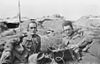 Australian signallers using a Marconi Mk III crystal receiver, 1916.
 Marconi Type 103 crystal set.
 SCR-54A crystal set used by US Signal Corps in World War I
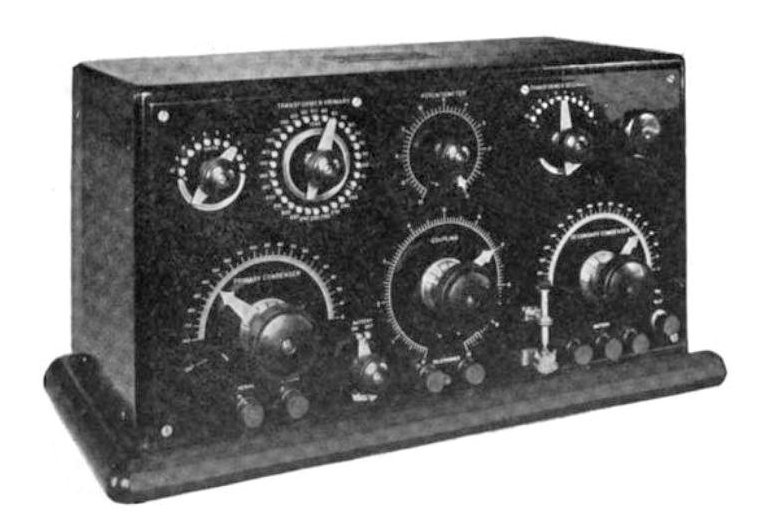
 Marconi Type 106 crystal receiver used for transatlantic communication, ca. 1921During the wireless telegraphy era before 1920, crystal receivers were "state of the art", and sophisticated models were produced.
 Homemade "loose coupler" set (top), Florida, ca. 1920
 Crystal radio, Germany, ca. 1924
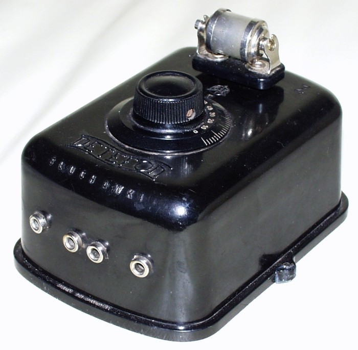
 Swedish "box" crystal radio with earphones, ca. 1925
 German Heliogen brand radio showing "basket-weave" coil, 1935
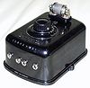 Polish Detefon brand radio, 1930-1939, using a "cartridge" type crystal (top)After 1920 crystal sets became the cheap alternative to vacuum tube radios, used in emergencies and by youth and the poor.
How it works
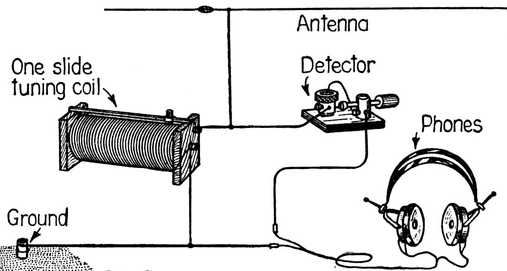
 Pictorial diagram from 1922 showing the circuit of a crystal radio. This common circuit did not use a tuning capacitor, but used the capacitance of the antenna to form the tuned circuit with the coil
A crystal radio can be thought of as a radio receiver reduced to its essentials.[3][26] It consists at a minimum of these components:[23][27][28]
- An antenna to pick up the radio waves and convert them to electric currents.
- A tuned circuit to select the signal of the radio station to be received, out of all the signals received by the antenna. This consists of a coil of wire called an inductor or tuning coil and a capacitor connected together, one or both of which is adjustable and can be used to tune in different stations. In some circuits a capacitor is not used, because the antenna also serves as the capacitor. The tuned circuit has a natural resonant frequency, and allows radio signals at this frequency to pass while rejecting signals at all other frequencies.
- A semiconductor crystal detector which extracts the audio signal (modulation) from the radio frequency carrier wave. It does this by only allowing current to pass through it in one direction, blocking half of the oscillations of the radio wave. This rectifies the alternating current radio wave to a pulsing direct current, whose strength varies with the audio signal. This current can be converted to sound by the earphone. Early sets used a cat's whisker detector, a fine wire touching the surface of a pebble of crystalline mineral such as galena. It was this component that gave crystal sets their name.
- An earphone to convert the audio signal to sound waves so they can be heard. The low power produced by crystal radios is insufficient to power an unamplified loudspeaker so earphones are used.
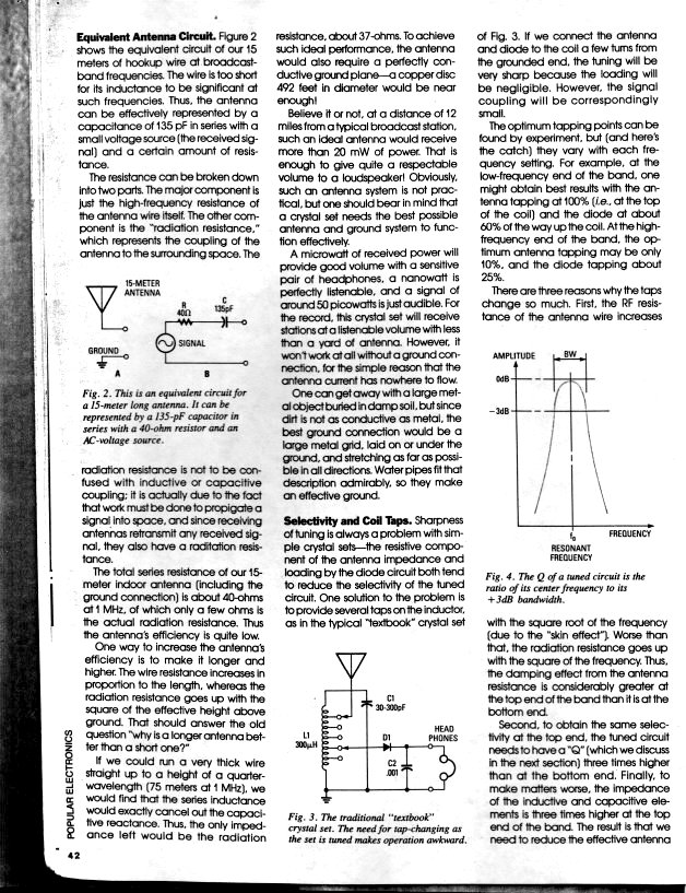
The sound power produced by the earphone of a crystal set comes solely from the radio station being received, via the radio waves picked up by the antenna.[3] The power picked up by a receiving antenna decreases with the square of its distance from the radio transmitter.[29] Even for a powerful commercial broadcasting station, if it is more than a few miles from the receiver the power received by the antenna is very small, typically measured in microwatts or nanowatts.[3] In modern crystal sets, signals as weak as 50 picowatts at the antenna can be heard.[30] Crystal radios can receive such weak signals without using amplification only due to the great sensitivity of human hearing,[3][31] which can detect sounds with a power of only 10−16 W/cm2.[32] Therefore crystal receivers have to be designed to convert the energy from the radio waves into sound as efficiently as possible. Even so, they are usually only able to receive nearby stations, within distances of about 25 miles for AM broadcast stations,[33][34] although the radiotelegraphy signals used during the wireless telegraphy era could be received at hundreds of miles,[34] and crystal receivers were even used for transoceanic communication during that period.
Passive receiver development was abandoned with the advent of reliable vacuum tubes around 1920, and subsequent crystal radio research was the work of radio amateurs and hobbyists.[35] Many different circuits have been used.[2][36][37] The following sections discuss the parts of a crystal radio in greater detail.
Antenna
The antenna converts the energy in the electromagnetic radio waves striking it to an alternating electric current in the antenna, which is connected to the tuning coil. Since in a crystal radio all the power comes from the antenna, it is important that the antenna collect as much power from the radio wave as possible. The larger an antenna, the more power it can intercept. In addition, antennas are most efficient when their length is close to a multiple of a quarter-wavelength of the radio waves they are receiving. Since the length of the waves used with crystal radios is very long (AM broadcast band waves are 182-566 m or 597–1857 ft. long)[38] the antenna is made as long as possible,[39] out of a long wire, in contrast to the whip antennas or ferrite loopstick antennas used in modern radios.
Serious crystal radio hobbyists use "inverted L" and "T" type antennas, consisting of hundreds of feet of wire suspended as high as possible between buildings or trees, with a feed wire attached in the center or at one end leading down to the receiver.[40][41] However more often random lengths of wire dangling out windows are used. A popular practice in early days (particularly among apartment dwellers) was to use existing large metal objects, such as bedsprings,[14] fire escapes, and barbed wire fences as antennas.[34][42][43]
Ground
The wire antennas used with crystal receivers are monopole antennas which develop their output voltage with respect to ground. They require a return circuit connected to ground (earth) so that the current from the antenna, after passing through the receiver, can flow into the ground. The ground wire is attached to a radiator, a water pipe, or a metal stake driven into the ground.[44][45] A good ground is more important for crystal sets than for powered receivers, because crystal sets have low input impedance to transfer power efficiently from the antenna, so significant current flows in the antenna/ground circuit. A low resistance ground connection (preferably below 25 Ω) is necessary because any resistance in the ground dissipates power from the antenna.[39] In contrast, modern receivers are voltage-operated devices, with high input impedance, so little current flows in the antenna/ground circuit. Also, mains powered receivers are grounded adequately through their power cords.
Tuned circuit
The tuned circuit, consisting of the coil and capacitor, acts as a resonator, analogous to a tuning fork for sound waves.[46] Electric charge flows rapidly back and forth between the plates of the capacitor through the coil, oscillating at the frequency of the radio signal. It has a high impedance at the desired radio signal's frequency, but a low impedance at all other frequencies,[47] so the desired signal is passed on to the detector which is connected across the tuned circuit, while the other signals are short-circuited to ground. The frequency of the station received is the resonant frequency f of the tuned circuit, determined by the capacitance C of the capacitor and the inductance L of the coil:[48]
 Fig. 2 In early crystal receivers the resonant antenna sometimes served as the tuned circuit.
In inexpensive sets the inductor had a sliding spring contact that pressed against the windings and could be slid up and down the coil, to allow a larger or smaller number of turns of the coil into the circuit, varying the inductance, to tune in different stations.[1] Alternatively, a variable capacitor is used to tune the radio instead of the coil.[49] Some modern crystal sets use a ferrite core tuning coil, in which the core is mounted on a threaded shaft and a knob turns the shaft, moving the core in and out of the coil, varying the inductance by changing the magnetic permeability.[50]
The antenna is itself a resonant circuit and its frequency can be shifted (tuned) with the reactance of inductors and/or capacitors in the radio. For the broadcast band, the antenna usually acts as a capacitor because antennas shorter than a quarter-wavelength have capacitive reactance to it can be tuned with a variable inductor[39] so many early crystal sets did not use a tuning capacitor. [51] They relied instead on the capacitance inherent in the wire antenna (in addition to significant parasitic capacitance in the coil itself[52]) to form the tuned circuit with the coil.
Some of the earliest crystal receivers (fig. 2) depended entirely on antenna resonance for tuning, and just consisted of a crystal detector D1 connected between the antenna and ground, with an earphone E1 across it.[1][51] When transmitting stations were rare, there was little need for frequency-selective elements besides the broad resonance of the antenna, so any station within a wide band of frequencies were heard in the earphone[35]. It was used in the earliest days of radio, transmitting stations were separated by large distances and wide frequency differences.
Impedance matching
 Fig. 3 "Two slider" circuit.[35] The two sliding contacts on the coil allowed the impedance of the radio to be adjusted to match the antenna as the radio was tuned, resulting in stronger reception.
An important principle used in crystal radio design to transfer maximum power to the earphone is impedance matching.[35][53][54] The maximum power is transferred from one part of a circuit to another when the impedance (resistance) of the two circuits is equal.[1][55][56] However in crystal sets, the impedance of the antenna-ground system (around 10-200 ohms[39]) is usually lower than the impedance of the receiver's tuned circuit (thousands of ohms at resonance),[57] and also varies depending on the quality of the ground, length of the antenna, and what frequency the receiver is tuned to in the band.[30] Therefore in better receiver circuits (fig. 4), to match the antenna impedance to the receiver's impedance, the antenna was connected across only a portion of the tuning coil's turns.[48][51] This made the coil L1 act as an impedance matching transformer (in an autotransformer connection) in addition to its tuning function. The tuned circuit's high impedance was transformed down by a factor equal to the square root of the turns ratio (the number of turns the antenna was connected across, to the total number of turns of the coil), to match the antenna impedance.[56] In the "two-slider" circuit (fig. 3), popular during the wireless era, both the antenna and the detector circuit were attached to the coil with sliding contacts, allowing (interactive)[58] adjustment of both the resonant frequency and the turns ratio.[59][60][61] Alternatively a multiposition switch ( S1, fig. 4) was used to select taps on the coil. These controls were adjusted until the station sounded loudest in the earphone.
The other place impedance matching was often used was between the tuning coil and the crystal detector/earphone circuit, to match the impedance of the detector.[1][35] To accomplish this the detector D1 , like the antenna, was connected to a tap on the coil.[62][63] This also improved the receiver's selectivity (see below).
Problem of selectivity

One of the drawbacks of crystal sets is that they are vulnerable to interference from stations near in frequency to the desired station; they have low selectivity.[2][4][30] Often two or more stations are heard simultaneously. This is because the simple tuned circuit doesn't reject nearby signals well; it allows through a wide band of frequencies, that is, it has a large bandwidth (low Q factor) compared to modern receivers.[4] This was a worse problem during the wireless era because the spark-gap transmitters of the era produced much wider bandwidth signals than modern transmitters, that spread interference over the frequencies of other stations.[4] The tuned circuit had wide bandwidth because the crystal detector connected across it had relatively low resistance which "loaded" the tuned circuit, damping the oscillations, reducing its Q.[30][64] In many circuits such as fig. 4 and 5, the selectivity was improved by connecting the detector and earphone circuit to a tap across only a fraction of the coil's turns.[35] This reduced the impedance loading of the tuned circuit, as well as improving the impedance match with the detector (see above).[35]
Inductively coupled receivers
 Fig. 5 Inductively-coupled circuit with impedance matching. This type was used in most quality crystal receivers.
 Amateur-built crystal receiver with "loose coupler" antenna transformer, Belfast, around 1914.
In more sophisticated crystal receivers, (fig. 5) the tuning coil was replaced with an adjustable air core antenna coupling transformer[1][35] (L1, L2) which improved the selectivity by a technique called loose coupling.[51][61][65] This consisted of two magnetically coupled coils of wire, one (the primary, L1) attached to the antenna and ground and the other (the secondary, L2) attached to the rest of the circuit. The current from the antenna created an alternating magnetic field in the primary coil, which induced a voltage in the secondary coil which was rectified and powered the earphone. Each of the coils functioned as a tuned circuit that was tuned to the frequency of the station: the primary coil resonated with the capacitance of the antenna (or sometimes another capacitor, C1), and the secondary resonated with the tuning capacitor C2. The two circuits interacted to form a resonant transformer. Reducing the coupling between the coils, by physically separating them so less of the magnetic field of one intersects the other (reducing the mutual inductance), narrows the bandwidth, resulting in much sharper, more selective tuning than a single tuned circuit.[51][66] However this involved a tradeoff; looser coupling also reduced the amount of signal getting through the transformer. So the transformer was made with adjustable coupling. One type common in early days, called a "loose coupler", consisted of a smaller coil inside a larger coil.[35][67] The smaller coil was mounted on a rack so it could be slid linearly in or out of the larger coil. If interference was encountered, the smaller coil would be slid further out of the larger, loosening the coupling and narrowing the bandwidth, to reject the interfering signal.
The antenna coupling transformer also functioned as an impedance matching transformer, to match the antenna impedance to the rest of the circuit. One or both of the coils usually had several taps which could be selected with a switch (S1), to adjust the turns ratio.
Coupling transformers were difficult to adjust, because the three adjustments, the tuning of the primary circuit, the tuning of the secondary circuit, and the coupling, were all interactive, and changing one affected the others.[68]
Crystal detector
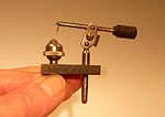 Galena cat's whisker detector
 Germanium diode used in modern crystal radios (about 3 mm long)
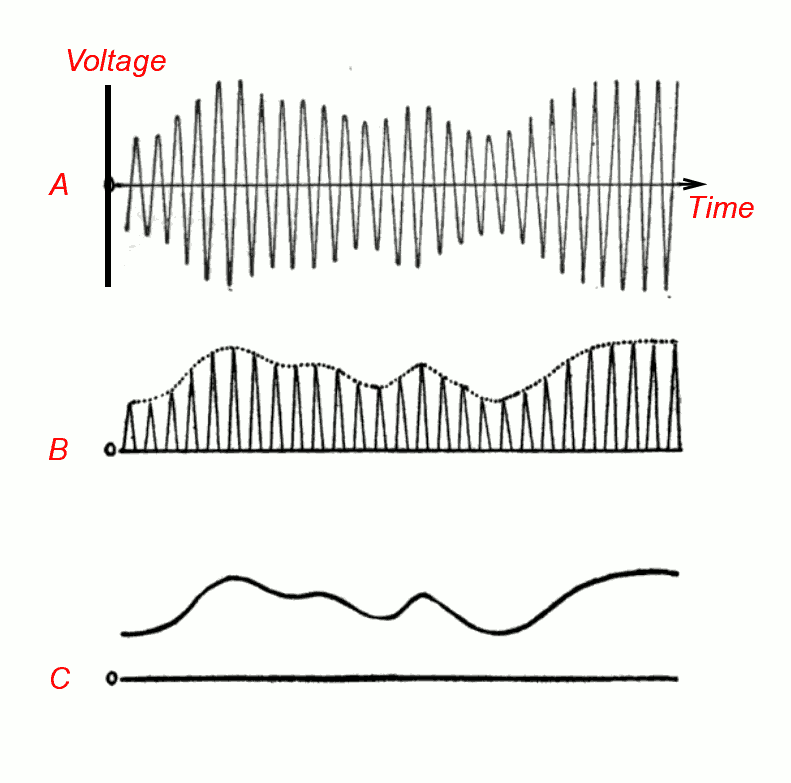
 Fig. 6 How the crystal detector works.[69][70] (A) The amplitude modulated radio signal from the tuned circuit. The rapid oscillations are the radio frequency carrier wave. The audio signal (the sound) is contained in the slow variations (modulation) of the size of the waves. This signal cannot be converted to sound by the earphone, because the audio excursions are the same on both sides of the axis, averaging out to zero, which would result in no net motion of the earphone's diaphragm. (B) The crystal conducts current better in one direction than the other, producing a signal whose amplitude does not average zero but varies with the audio signal. (C) Sometimes a bypass capacitor is used to remove the radio frequency carrier pulses, leaving the audio signal.
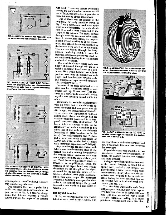
In early sets, this was a cat's whisker detector, a fine metal wire on an adjustable arm that touched the surface of a crystal of a semiconducting mineral.[1][6][71] This formed a crude unstable semiconductor diode (Schottky diode), which allowed current to flow better in one direction but than in the opposite direction.[72] Modern crystal sets use modern semiconductor diodes.[64] The detector rectified the alternating current radio signal to a pulsing direct current, which had the audio modulation signal impressed on it, so it could be converted to sound by the earphone, which was connected in series (or sometimes in parallel) with the detector.[23][70]
The rectified current from the detector still had radio frequency pulses from the carrier in it, which for some wavelengths did not pass well through the high inductance of the earphones. In those cases, a small capacitor, called a blocking or bypass capacitor (C2, fig. 4 and C3, fig. 5), was usually placed across the earphone terminals to bypass these pulses around the earphone to ground,[73] although the earphone cord usually had enough capacitance that this component could be omitted.[31][51]
In a cat's whisker detector only certain sites on the crystal surface functioned as rectifying junctions, and the device was very sensitive to the pressure of the crystal-wire contact, which could be disrupted by the slightest vibration.[6][74] Therefore a usable contact point had to be found by trial and error before each use. The operator dragged the wire across the crystal surface until a radio station or "static" sounds were heard in the earphones.[75] An alternative adjustment method was to use a battery-powered buzzer (BZ, fig. 7) attached to the ground wire to provide a test signal.[75] The spark at the buzzer's electrical contacts served as a weak radio transmitter, so when the detector began working the buzz could be heard in the earphones, and the buzzer was then turned off.
 "Foxhole radio" using a battery carbon touching a razor blade for a detector (left), Greece, 1935
Galena (lead sulfide) was probably the most common crystal used in cat's whisker detectors,[61][74] but various other types of crystals were also used, such as iron pyrite (Fool's gold, Fe2S), silicon, molybdenite (MoS2), silicon carbide (carborundum, SiC), and a zincite-bornite (ZnO-Cu5FeS4) crystal-to-crystal junction trade-named Perikon.[31][76] Crystal radios have also been made with rectifying junctions improvised from a variety of common objects, such as blue steel razor blades and lead pencils,[31][77] rusty needles,[78] and pennies[31] In these, a semiconducting layer of oxide or sulfide on the metal surface is usually responsible for the rectifying action.[31]
In modern sets a semiconductor diode is used, which is much more reliable than a cat's whisker detector and doesn't require any adjustments.[31][64][79] Germanium diodes (or sometimes Schottky diodes) are used instead of silicon diodes, because their lower forward voltage drop (roughly 0.3V compared to 0.6V[63]) makes them more sensitive.[64][80]
All semiconductor detectors function rather inefficiently in crystal receivers, because the low voltage signal level is too low to result in much difference between forward better conduction and reverse weaker conduction. Bias can move the diode's operating point higher on the detection curve to produce more signal voltage at the expense of less signal current (higher impedance). There is a limit to the benefit that this produces, depending on the other impedances of the radio. To improve the sensitivity of some of the early crystal detectors, such as silicon carbide, a small forward bias voltage was applied across the detector by a battery and potentiometer (B1, R1, fig. 7) .[81][82] This improved sensitivity by moving the DC operating point to a more desirable voltage-current operating point (impedance) on the junction's I-V curve.
Earphones
 Fig. 7 Circuit with detector bias battery (B1) to improve sensitivity and buzzer (BZ) to adjust cat's whisker.
The requirements for earphones used in crystal sets are different from earphones used with modern audio equipment. They have to be efficient at converting the electrical signal energy to sound waves, while most modern earphones are designed for high fidelity reproduction of the sound.[83] In early homebuilt sets, the earphones were the most costly component.[84]
The early earphones used with wireless-era crystal sets had moving iron drivers that worked similarly to loudspeakers. Each earpiece contained a magnet wound with coils of wire to form an electromagnet, with poles close to a steel diaphragm. When the audio signal from the radio was passed through the electromagnet's windings, it created a varying magnetic field that pulled on the diaphragm, causing it to vibrate. The vibrations of the diaphragm pushed and pulled on the air in front of it, creating sound waves. Standard headphones used in telephone work had a low impedance, often 75 Ω, and required more current than a crystal radio could supply, so the type used with radios was wound with more turns of finer wire and had an impedance of 2000-8000 Ω.[85][86][87]
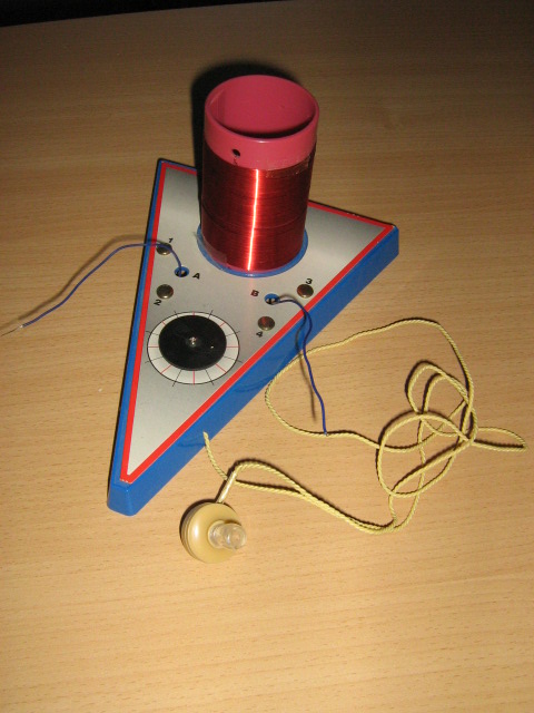
 Modern crystal radio with piezoelectric earphone
Modern crystal sets use piezoelectric crystal earpieces, which are much more sensitive and also smaller.[83] They consist of a piezoelectric crystal with electrodes attached to each side, glued to a light diaphragm. When the audio signal from the radio set is applied to the electrodes, it causes the crystal to vibrate, vibrating the diaphragm. Crystal earphones are designed as ear buds that plug directly into the ear canal of the wearer, coupling the sound more efficiently to the eardrum. Their resistance is much higher, typically megohms, so they don't "load" the tuned circuit; increasing the selectivity of the receiver. However the earphone's higher resistance, in parallel with its capacitance of around 9 pF, creates a low pass filter which removes the higher audio frequencies, distorting or eliminating the sound.[88] So a bypass capacitor is not needed (although in practice a small one of around 680pFd to .001 uFd is often used to help improve quality), and instead a 10-100 KΩ resistor must be added across the earphone's input.[89]
Modern low impedance (8 Ω) earphones cannot be used unmodified in crystal sets because the receiver doesn't produce enough current to drive them. They are sometimes used by adding an audio transformer to match their impedance with the higher impedance of the circuit.
History
 A family listening to a crystal radio in the 1920s
Crystal radio was invented by a long, partly obscure chain of discoveries in the late 19th century that gradually evolved into more and more practical radio receivers in the early 20th century; and constitutes the origin of the field of electronics. The earliest practical use of crystal radio was to receive Morse code radio signals transmitted by early amateur radio experimenters using very powerful spark-gap transmitters. As electronics evolved, the ability to send voice signals by radio caused a technological explosion in the years around 1920 that evolved into today's radio broadcasting industry.
Early years
Early radio telegraphy used spark gap and arc transmitters as well as high-frequency alternators running at radio frequencies. At first a Branley Coherer was used to indicate the presence of a radio signal. However, these lacked the sensitivity to convert weak signals.
In the early 20th century, various researchers discovered that certain metallic minerals, such as galena, could be used to detect radio signals. In 1901, Sir Jagadish Chandra Bose filed for a US patent for "A Device for Detecting Electrical Disturbances" that mentioned the use of a galena crystal; this was granted in 1904, #755840. However, his work, and the patent, went somewhat unnoticed in the western scientific world, as on August 30, 1906, Greenleaf Whittier Pickard filed a patent for a silicon crystal detector, which was granted on November 20, 1906. Pickard's detector was revolutionary in that he found that a fine pointed wire known as a "cat's whisker", in delicate contact with a mineral produced the best semiconductor effect. A crystal detector includes a crystal, a special thin wire that contacts the crystal and the stand that holds the components in place. The most common crystal used is a small piece of galena; pyrite was also often used, as it was a more easily adjusted and stable mineral, and quite sufficient for urban signal strengths. Several other minerals also performed well as detectors. Another benefit of crystals was that they could demodulate amplitude modulated signals. This mode was used in radiotelephones and to broadcast voice and music for a public audience. Crystal sets represented an inexpensive and technologically simple method of receiving these signals at a time when the embryonic radio broadcasting industry was beginning to grow.
 Greenleaf Whittier Pickard's U.S. Patent 836,531 "Means for receiving intelligence communicated by electric waves" diagram.
In 1922 the (then named) U.S. Bureau of Standards released a publication entitled, Construction and Operation of a Simple Homemade Radio Receiving Outfit.[90] This article showed how almost any family having a member handy with simple tools could make a radio and tune in to weather, crop prices, time, news and the opera. This design was significant in bringing radio to the general public. NBS followed that with more selective two-circuit version Construction and Operation of a Two-Circuit Radio Receiving Equipment With Crystal Detector that was published the same year [91] and is still frequently built by enthusiasts today.
1920s and 1930s
 NBS Circular 120 Home Crystal Radio Project.
In the beginning of the 20th century, radio had little commercial use and radio experimentation was a hobby for many people. .[92] Some historians consider the Autumn of 1920 to be the beginning of commercial radio broadcasting for entertainment purposes. Pittsburgh, PA, station KDKA, owned by Westinghouse, received its license from the United States Department of Commerce just in time to broadcast the Harding-Cox presidential election returns. In addition to reporting on special events, broadcasts to farmers of crop price reports were an important public service, in the early days of radio.
In 1921, factory-made radios were very expensive. Since less affluent families could not afford to own one, newspapers and magazines carried articles on how to build a crystal radio with common household items. To minimize the cost, many of the plans suggested winding the tuning coil on empty pasteboard containers such as oatmeal boxes, which became a common foundation for homemade radios.
Valveless amplifier
A "Carbon amplifier" consisting of a carbon microphone and an electromagnetic earpiece sharing a common membrane and case. This was used in the telephone industry and in hearing aids nearly since the invention of both components and long before vacuum tubes. This could be readily bought or made from surplus telephone parts for use with a crystal radio. Unlike vacuum tubes, it could run with only a flashlight or car battery and had an indefinite lifetime.
Crystodyne
 Crystodyne. View of an experimental panel with a generator and a crystal detector, collected in the laboratory of "News Radio ". In the picture numbers denote the following parts: 1 - vario 2 - variable capacitor, 3 - Cellular coil, 4 - condenser 5nf 5 - Throttle 6 - Potentiometer; 7 - Switch 8 - Resistance 9 - Detector zinc-steel, 10 - the headphone jack, 11 - jack batteries.
In the early 1920s Russia, devastated by civil war, Oleg Losev was experimenting with applying voltage biases to various kinds of crystals for manufacture of radio detectors. The result was astonishing - with a zincyte (zinc oxide) crystal he gained amplification.[93][94] This was negative resistance phenomenon, decades before the tunnel diode. After the first experiments, he built regenerative and superheterodyne receivers, and even transmitters. However, this discovery was not supported by authorities and soon forgotten and no device was produced in mass quantity beyond a few examples for research. Crystodyne was produced in primitive conditions; it can be made in a rural forge - unlike vacuum tubes and modern semiconductor devices.
1940s
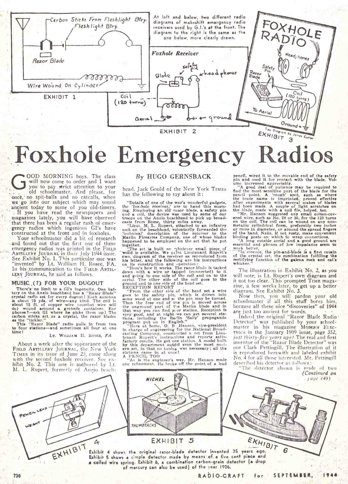
When Allied troops were halted near Anzio, Italy during the spring of 1944, personal portable radios were strictly prohibited as the Germans had radio detecting equipment that could detect the local oscillator signal of superheterodyne receivers. Crystal sets lack local oscillators, so they cannot be detected in this way. Some resourceful GIs found that a crude crystal set could be made from a coil made of salvaged wire, a rusty razor blade and a pencil lead for a diode. By lightly touching the pencil lead to spots of blue on the blade, or to spots of rust, they formed what is called a point contact diode and the rectified signal could be heard on headphones or crystal ear pieces. The idea spread across the beachhead, to other parts of the war, and to popular culture. The sets were dubbed "foxhole receivers" by the popular press, and they became part of the folklore of World War II.
In some Nazi occupied countries there were widespread confiscations of radio sets from the civilian population. This led to particularly determined listeners building their own "clandestine receivers" which frequently amounted to little more than a basic crystal set. However anyone doing so risked imprisonment or even death if caught and in most parts of Europe the signals from the BBC (or other allied stations) were not strong enough to be received on such a set. However there were places such as the Channel Islands and Netherlands where it was possible.
Later years
While it never regained the popularity and general use that it enjoyed at its beginnings, the circuit is still used. The Boy Scouts (who emerged as the unofficial custodians of crystal radio lore) kept construction of a set in their program since the 1920s. A large number of prefabricated novelty items and simple kits could be found through the 1950s and 1960s, and many children with an interest in electronics built one.
Building crystal radios was a craze in the 1920s, and again in the 1950s. Recently, hobbyists have started designing and building sophisticated examples of the instruments. Much effort goes into the visual appearance of these sets as well as their performance, and some outstanding examples can be found. Annual crystal radio 'DX' contests(long distance reception) and building contests allow these set owners to compete with each other and form a community of interest in the subject.
Attempts at recovering RF carrier power
A crystal radio tuned to a strong local transmitter can be used just as a power source for a second amplified receiver for distant stations that cannot be heard with a plain crystal radio.[95]
There is a long history of unsuccessful attempts and unverified claims to recover the power in the carrier of the received signal itself. Traditional crystal sets use half-wave rectifiers. As AM signals have a modulation factor of only 30% by voltage at peaks[citation needed], no more than 9% of received signal power (P = U2 / R) is actual audio information, and 91% is just rectified DC voltage. Given that the audio signal is unlikely to be at peak all the time, the ratio of energy is, in practice, even greater. Considerable effort was made to convert this DC voltage into sound energy. Some earlier attempts include a one-transistor[96] amplifier in 1966. Sometimes efforts to recover this power are confused with other efforts to produce a more efficient detection.[97] This history continues now with designs as elaborate as "inverted two-wave switching power unit".[95]
See also
Notes
- ^ a b c d e f g Carr, Joseph J. (1990). Old Time Radios! Restoration and Repair. USA: McGraw-Hill Professional. pp. 7–9. ISBN 0830633421. http://books.google.com/books?id=OVHYa_S2nKIC&pg=PA7.
- ^ a b c Petruzellis, Thomas (2007). 22 Radio and Receiver Projects for the Evil Genius. US: McGraw-Hill Professional. pp. 40, 44. ISBN 9780071489294. http://books.google.com/books?id=AJBBf5hCYqIC&pg=PA40.
- ^ a b c d e Field, Simon Quellen (2003). Gonzo gizmos: Projects and devices to channel your inner geek. USA: Chicago Review Press. p. 85. ISBN 9781556525209. http://books.google.com/books?id=t-N1KdTb0FwC&pg=PT97.
- ^ a b c d Schaeffer, Derek K.; Thomas H. Lee (1999). The Design and Implementation of Low Power CMOS Receivers. Springer. pp. 3–4. ISBN 0792385187. http://books.google.com/books?id=4IDLK8NMDBQC&pg=PA4.
- ^ Braun, Ernest; Stuart MacDonald (1982). Revolution in Miniature: The history and impact of semiconductor electronics, 2nd Ed.. UK: Cambridge Univ. Press. pp. 11–12. ISBN 9780521289030. http://books.google.com/books?id=03c4wldf-k4C&pg=PA11.
- ^ a b c Riordan, Michael; Lillian Hoddeson (1988). Crystal fire: the invention of the transistor and the birth of the information age. USA: W. W. Norton & Company. pp. 19–21. ISBN 0393318516. http://books.google.com/books?id=SZ6wm5ZSUmsC&pg=PA92.
- ^ Sarkar, Tapan K. (2006). History of wireless. USA: John Wiley and Sons. p. 333. ISBN 0471718149,. http://books.google.com/books?id=NBLEAA6QKYkC&pg=PA333.
- ^ Bose was first to use a crystal as a radio wave detector, using galena detectors to receive microwaves starting around 1894 and receiving a patent in 1904. Emerson, D. T. (Dec. 1997). "The work of Jagadish Chandra Bose: 100 years of mm wave research". IEEE Transactions on Microwave Theory and Techniques 45 (12): 2267–2273. doi:10.1109/22.643830. http://books.google.com/books?id=09Zsv97IH1MC&pg=PA88. Retrieved 2010-01-19.
- ^ Sarkar (2006) History of wireless, p.94, 291-308
- ^ Douglas, Alan (April 1981). "The crystal detector". IEEE Spectrum (New York: Inst. of Electrical and Electronic Engineers): 64. http://www.crystalradio.net/crystalplans/xximages/thecrystaldetector1.jpg. Retrieved 2010-03-14. on Stay Tuned website
- ^ a b Basalla, George (1988). The Evolution of Technology. UK: Cambridge University Press. p. 44. ISBN 0521296811. http://books.google.com/books?id=EBtnG36-1WIC&pg=PA44.
- ^ crystal detectors were used in receivers in greater numbers than any other type of detector after about 1907. Marriott, Robert H. (September 17, 1915). "United States Radio Development". Proc. of the Inst. of Radio Engineers (USA: Institute of Radio Engineers) 5 (3): 184. http://books.google.com/books?id=bh0B93CuXnkC&pg=PA184. Retrieved 2010-01-19.
- ^ Corbin, Alfred (2006). The Third Element: A Brief History of Electronics. AuthorHouse. pp. 44–45. ISBN 1420890840. http://books.google.com/books?id=-9lt4HL-AlwC&pg=PA45.
- ^ a b Kent, Herb; David Smallwood, Richard M. Daley (2009). The Cool Gent: The Nine Lives of Radio Legend Herb Kent. US: Chicago Review Press. pp. 13–14. ISBN 1556527748. http://books.google.com/books?id=f92pJ3JhaJYC&pg=PT33.
- ^ Jack Bryant (2009) Birmingham Crystal Radio Group, Birmingham, Alabama, USA . Retrieved 2010-01-18.
- ^ The Xtal Set Society midnightscience.com . Retrieved 2010-01-18.
- ^ Darryl Boyd (2006) Stay Tuned Crystal Radio website . Retrieved 2010-01-18.
- ^ Al Klase Crystal Radios, Klase's SkyWaves website . Retrieved 2010-01-18.
- ^ Mike Tuggle (2003) Designing a DX crystal set Antique Wireless Association journal . Retrieved 2010-01-18.
- ^ Rainer Steinfuehr (2009) Gollum´s Crystal Receiver World Wumpus's Old Radio World website, Berlin, Germany. Retrieved 2010-01-18.
- ^ Elmer Memorial Crystal Radio DX Contest, sponsored by Birmingham Crystal Radio Group, Birmingham, Alabama, USA . Retrieved 2010-01-18.
- ^ Crystal Radio Building Contest, by The Xtal Set Society midnightscience.com . Retrieved 2010-01-18.
- ^ a b c Williams, Lyle R. (2006). The New Radio Receiver Building Handbook. The Alternative Electronics Press. pp. 20–23. ISBN 184728526. http://books.google.com/books?id=XiKgKdeBi6cC&pg=PT20.
- ^ Lescarboura, Austin C. (1922). Radio for Everybody. New York: Scientific American Publishing Co.. pp. 4, 110, 268. http://books.google.com/books?id=pf0WAAAAYAAJ&pg=PA110.
- ^ Long distance transoceanic stations of the era used wavelengths of 10,000 to 20,000 meters, correstponding to frequencies of 15 to 30 kHz.Morecroft, John H.; A. Pinto, Walter A. Curry (1921). Principles of Radio Communication. New York: John Wiley & Sons.. p. 187. http://books.google.com/books?id=jusOAAAAYAAJ&pg=PA187.
- ^ Purdie, Ian C. (2001). "Crystal Radio Set". electronics-tutorials.com. Ian Purdie. http://www.electronics-tutorials.com/receivers/crystal-radio-set.htm. Retrieved 2009-12-05.
- ^ Lescarboura, Austin C. (1922). Radio for Everybody. New York: Scientific American Publishing Co.. pp. 93–94. http://books.google.com/books?id=pf0WAAAAYAAJ&pg=PA93.
- ^ Kuhn, Kenneth A. (Jan. 6, 2008). "Introduction". Crystal Radio Engineering. Prof. Kenneth Kuhn website, Univ. of Alabama. http://www.kennethkuhn.com/students/crystal_radios/introduction.pdf. Retrieved 2009-12-07.
- ^ Fette, Bruce A. (Dec. 27, 2008). "RF Basics: Radio Propagation". RF Engineer Network. http://www.rfengineer.net/1170/rf-basics-radio-propagation/. Retrieved 2010-01-18.
- ^ a b c d Payor, Steve (June 1989). "Build a Matchbox Crystal Radio". Popular Electronics: 42. http://www.crystalradio.net/crystalplans/xximages/matchbox2.jpg. Retrieved 2010-05-28. on Stay Tuned website
- ^ a b c d e f g Lee, Thomas H. (2004). Planar Microwave Engineering: A practical guide to theory, measurement, and circuits. UK: Cambridge Univ. Press. pp. 297–304. ISBN 9780521835268. http://books.google.com/books?id=uoj3IWFxbVYC&pg=PA299.
- ^ Nave, C. Rod. "Threshold of hearing". HyperPhysics. Dept. of Physics, Georgia State University. http://hyperphysics.phy-astr.gsu.edu/hbase/HFrame.html. Retrieved 2009-12-06.
- ^ Lescarboura, 1922, p. 144
- ^ a b c Binns, Jack (November 1922). "Jack Binn's 10 commandments for the radio fan". Popular Science (New York: Modern Publishing Co.) 101 (5): 42–43. http://books.google.com/books?id=pSkDAAAAMBAJ&pg=PA42. Retrieved 2010-01-18.
- ^ a b c d e f g h i j Klase, Alan R. (1998). "Crystal Set Design 102". Skywaves. Alan Klase personal website. http://www.skywaves.ar88.net/xtalset102/xtalset102.htm. Retrieved 2010-02-07.
- ^ a list of circuits from the wireless era can be found in Sleeper, Milton Blake (1922). Radio hook-ups: a reference and record book of circuits used for connecting wireless instruments. USA: The Norman W. Henley publishing co.. pp. 7–18. http://books.google.com/books?id=k8Wpg2wxDLcC.
- ^ May, Walter J. (1954). The Boy's Book of Crystal Sets. London: Bernard's. http://books.google.com/books?id=9Bs5PwAACAAJ&dq=Walter+May+Boy's+book+of+crystal+sets+intitle:Boy's+intitle:book+intitle:of+intitle:crystal+intitle:sets+inauthor:Walter+inauthor:May. is a collection of 12 circuits
- ^ Purdie, Ian (1999). "A Basic Crystal Set". Ian Purdie's Amateur Radio Pages. personal website. http://my.integritynet.com.au/purdic/crystal_set.htm. Retrieved 2010-02-27.
- ^ a b c d Kuhn, Kenneth (Dec. 9, 2007). "Antenna and Ground System". Crystal Radio Engineering. Kenneth Kuhn website, Univ. of Alabama. http://www.kennethkuhn.com/students/crystal_radios/antenna_and_ground_system.pdf. Retrieved 2009-12-07.
- ^ Marx,, Harry J.; Adrian Van Muffling (1922). Radio Reception: A simple and complete explanation of the principles of radio telephony. USA: G.P. Putnam's sons. pp. 130–131. http://books.google.com/books?id=BgY9AAAAYAAJ&pg=PA130.
- ^ Williams, Henry Smith (1922). Practical Radio. New York: Funk and Wagnalls. p. 58. http://books.google.com/books?id=-CwwAAAAYAAJ&pg=PA58.
- ^ Putnam, Robert (October 1922). "Make the aerial a good one". Tractor and Gas Engine Review (New York: Clarke Publishing Co.) 15 (10): 9. http://books.google.com/books?id=XMTmAAAAMAAJ&pg=RA6-PA9. Retrieved 2010-01-18.
- ^ Lescarboura 1922, p.100
- ^ Collins, Archie Frederick (1922). The Radio Amateur's Hand Book. USA: Forgotten Books. pp. 18–22. ISBN 1606801198. http://books.google.com/books?id=jpMi0V8qoKsC&pg=PA18.
- ^ Lescarboura, 1922, p. 102-104
- ^ Hausmann, Erich, Ed. (1922). Radio Phone Receiving; a Practical Book for Everybody. New York: D. Van Nostrand. p. 48. ISBN 1110371594. http://books.google.com/books?id=6qFRAAAAMAAJ&pg=PA48.
- ^ Hayt, William H.; Jack E. Kemmerly (1971). Engineering Circuit Analysis, 2nd Ed.. New York: McGraw-Hill. pp. 398–399. ISBN 070273820.
- ^ a b Kuhn, Kenneth A. (Jan. 6, 2008). "Resonant Circuit". Crystal Radio Engineering. Prof. Kenneth Kuhn website, Univ. of Alabama. http://www.kennethkuhn.com/students/crystal_radios/resonant_circuit.pdf. Retrieved 2009-12-07.
- ^ Clifford, Martin (July 1986). "The early days of radio". Radio Electronics: 61–64. http://www.crystalradio.net/crystalplans/xximages/earlydays3.jpg. Retrieved 2010-07-19. on Stay Tuned website
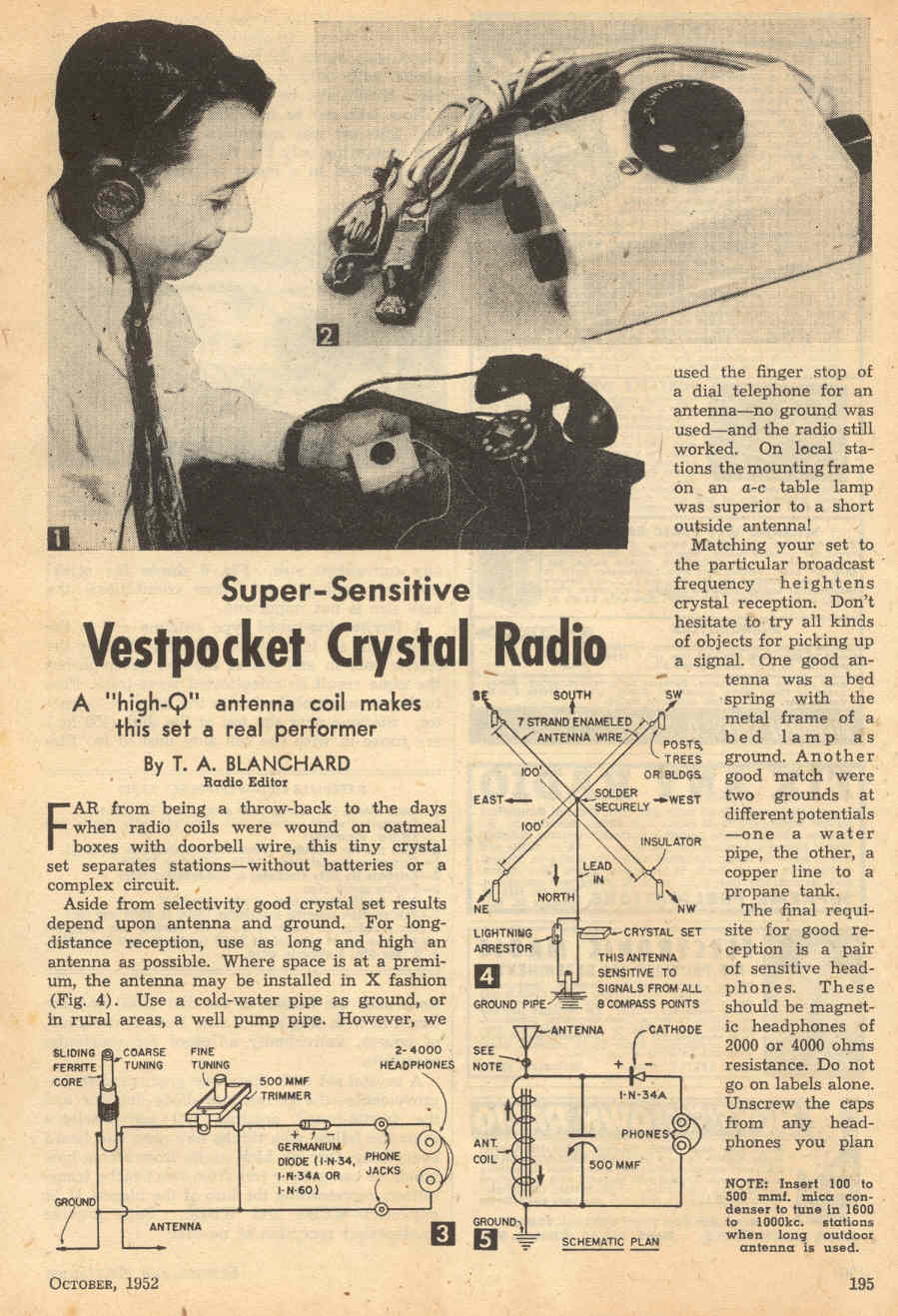
- ^ Blanchard, T. A. (October 1962). "Vestpocket Crystal Radio". Radio-electronics: 196. http://crystalradio.net/crystalplans/xximages/vestpocketradio1.jpg. Retrieved 2010-08-19. on Crystal Radios and Plans, Stay Tuned website
- ^ a b c d e f The Principles Underlying Radio Communication, 2nd Ed., Radio pamphlet no. 40. USA: Prepared by US National Bureau of Standards, United States Army Signal Corps. 1922. pp. 421–425. http://books.google.com/books?id=4JVEAAAAIAAJ&pg=PA422.
- ^ Hausmann 1922, p. 57
- ^ Paul J. Nahin, Paul J. (2001). The science of radio: with MATLAB and Electronics Workbench demonstrations. USA: Springer. pp. 60–62. ISBN 0387951504. http://books.google.com/books?id=V1GBW6UD4CcC&pg=PA61.
- ^ Technical discussions of impedance matching in crystal radios can be found in Ben H. Tongue (2007) Practical considerations, etc., Crystal Radio Set Systems: Design, Measurement, and Improvement; Ben Tongue personal website and Berthold Bosch (2002) Crystal Set analysis, Gollum's Crystal Receiver World
- ^ Smith, K. c. a.; R. E. Alley (1992). Electrical circuits: An introduction. UK: Cambridge University Press. p. 218. ISBN 0521377692. http://books.google.com/books?id=Aj9blWqYg2YC&pg=PA217.
- ^ a b Alley, Charles L.; Kenneth W. Atwood (1973). Electronic Engineering, 3rd Ed.. New York: John Wiley & Sons. p. 269. ISBN 0471024503.
- ^ Tongue, Ben H. (2007-11-06). "Practical considerations, helpful definitions of terms and useful explanations of some concepts used in this site". Crystal Radio Set Systems: Design, Measurement, and Improvement. Ben Tongue personal website. http://www.bentongue.com/xtalset/0def_exp/0def_exp.html. Retrieved 2010-02-07.
- ^ Bucher, Elmer Eustace (1921). Practical Wireless Telegraphy: A complete text book for students of radio communication, Revised Ed.. New York: Wireless Press, Inc. p. 133. http://books.google.com/books?id=DI9RAAAAMAAJ&pg=PA134.
- ^ Marx & Van Muffling (1922) Radio Reception, p.94
- ^ Stanley, Rupert (1919). Textbook on Wireless Telegraphy, Vol. 1. London: Longman's Green & Co.. pp. 280–281. http://books.google.com/books?id=LLhRAAAAMAAJ&pg=PA284.
- ^ a b c Collins, Archie Frederick (1922). The Radio Amateur's Hand Book. USA: Forgotten Books. pp. 23–25. ISBN 1606801198. http://books.google.com/books?id=jpMi0V8qoKsC&pg=PA25.
- ^ Kuhn, Kenneth (March 1, 2008). "Tapping Inductors". Crystal Radio Engineering. Kenneth Kuhn website, Univ. of Alabama. http://www.kennethkuhn.com/students/crystal_radios/tapping_inductors.pdf. Retrieved 2009-12-07.
- ^ a b Hadgraft, Peter. "The Crystal Set 5/6". The Crystal Corner. Kev's Vintage Radio and Hi-Fi page. http://oldkevspage.tripod.com/wr/xtal3.html. Retrieved 2010-05-28.
- ^ a b c d Wenzel, Charles (1995). "Simple crystal radio". Crystal radio circuits. techlib.com. http://www.techlib.com/electronics/crystal.html. Retrieved 2009-12-07.
- ^ Hogan, John V. L. (October 1922). "The Selective Double-Circuit Receiver". Radio Broadcast (New York: Doubleday Page & Co.) 1 (6): 480–483. http://books.google.com/books?id=VMcnAAAAYAAJ&pg=RA5-PA480. Retrieved 2010-02-10.
- ^ Alley & Atwood (1973) Electronic Engineering, p. 318
- ^ Marx & Van Muffling (1922) Radio Reception, p.96-101
- ^ U.S. Signal Corps (October 1916). Radiotelegraphy. USA: Government Printing Office. p. 70. http://books.google.com/books?id=PbRBAAAAIAAJ&pg=PA70.
- ^ Marx & Van Muffling (1922) Radio Reception, p.43, fig.22
- ^ a b Campbell, John W. (October 1944). "Radio Detectors and How They Work". Popular Science (New York: Popular Science Publishing Co.) 145 (4): 206–209. http://books.google.com/books?id=PyEDAAAAMBAJ&pg=PA206&. Retrieved 2010-03-06.
- ^ Harte, Bernard (2002). When Radio Was the Cat's Whiskers. Rosanberg. pp. 149–150. ISBN 1877058084. http://books.google.com/books?id=IEnPtx0M2EEC&pg=PA149.
- ^ Lee, Thomas H. (2004). The Design of CMOS Radio-Frequency Integrated Circuits. UK: Cambridge University Press. pp. 4–6. ISBN 0521835399. http://books.google.com/books?id=DzcMK-2mFQUC&printsec=frontcover&dq=Lee+CMOS+radio+frequency+integrated+circuits&cd=1#v=onepage&q=crystal%20detector&f=false.
- ^ Stanley (1919) Text-book on Wireless Telegraphy, p.282
- ^ a b Hausmann (1922), p.60-61
- ^ a b Lescarboura (1922), p.143-146
- ^ Stanley (1919), p. 311-318
- ^ Gernsback, Hugo (September 1944). "Foxhole emergency radios". Radio-Craft (New York: Radcraft Publications) 16 (1): 730. http://www.crystalradio.net/crystalplans/xximages/foxholeemergencyradios1.jpg. Retrieved 2010-03-14. on Crystal Plans and Circuits, Stay Tuned website
- ^ Douglas, Alan (April 1981). "The Crystal Detector". IEEE Spectrum (Inst. of Electrical and Electronic Engineers) 18 (4): 64–65. http://www.crystalradio.net/crystalplans/xximages/thecrystaldetector1.jpg. Retrieved 2010-03-28.
- ^ Kuhn, Kenneth A. (Jan. 6, 2008). "Diode Detectors". Crystal Radio Engineering. Prof. Kenneth Kuhn website, Univ. of Alabama. http://www.kennethkuhn.com/students/crystal_radios/diode_detectors.pdf. Retrieved 2009-12-07.
- ^ Kleijer, Dick. "Diodes". crystal-radio.eu. http://www.crystal-radio.eu/endiodes.htm. Retrieved 2010-05-27.
- ^ The Principles Underlying Radio Communication (1922), p.439-440
- ^ Bucher, Elmer Eustace (1921). Practical Wireless Telegraphy: A complete text book for students of radio communication, Revised Ed.. New York: Wireless Press, Inc. pp. 134–135. http://books.google.com/books?id=DI9RAAAAMAAJ&pg=PA134.
- ^ a b Field 2003, p.93-94
- ^ Lescarboura (1922), p.285
- ^ Collins (1922), p. 27-28
- ^ Williams (1922), p. 79
- ^ The Principles Underlying Radio Communication (1922), p. 441
- ^ Payor, Steve (June 1989). "Build a Matchbox Crystal Radio". Popular Electronics: 45. http://www.crystalradio.net/crystalplans/xximages/matchbox5.jpg. Retrieved 2010-05-28.
- ^ Field (2003), p. 94
- ^ [1]
- ^ [2]
- ^ Bondi, Victor."American Decades:1930-1939"
- ^ Peter Robin Morris, A history of the world semiconductor industry, IET, 1990, ISBN 0863412270, page 15
- ^ http://earlyradiohistory.us/1924cry.htm
- ^ a b Polyakov V.T. "Simple receivers for AM signals", ISBN 5-94074-056-1 (in Russian)
- ^ Radio-Electronics, 1966, №2
- ^ QST [Amateur Radio Magazine] January 2007, "High Sensitivity Crystal Set" <http://www.arrl.org/qst/2007/01/culter.pdf>
External links
- The Xtal Set Society, Dedicated to once again building and experimenting with radio electronics.
- Building a simple crystal radio.Field, Simon Quellen, Scitoys.
- Stay Tuned. Crystal radio plans and projects.
- Build the Mystery Crystal set A simple and surprisingly effective and sensitive design.
- Shortwave Mystery Crystal Radio A shortwave version of the Mystery Crystal Set by KC4IWT.
- A website that lots of information on early radio and crystal sets
- Hobbydyne Crystal Radios History and Technical Information on Crystal Radios
- Ben Tongue's Technical Talk Section 1 links to "Crystal Radio Set Systems: Design, Measurements and Improvement".
- "Semiconductor archeology or tribute to unknown precusors". earthlink.net/~lenyr.
- Nyle Steiner K7NS, Zinc Negative Resistance RF Amplifier for Crystal Sets and Regenerative Receivers Uses No Tubes or Transistors. November 20, 2002.
- Crystal Set DX? Roger Lapthorn G3XBM
- Building a crystal radio set A guide to building a simple crystal radio receiver.
- Website which has a large selection of homebuilt crystal and tube radios built by Dave Schmarder.
- The Bose Institute
- Varun Aggarwal of MIT's page on Bose
- British Crystal Set Definitive Information.
Patents
- U.S. Patent 836,531 "Means for receiving intelligence communicated by electric waves", 1906. G. W. Pickard.
- U.S. Patent 876,996 "Intelligence intercommunication by magnetic wave components", 1908. G. W. Pickard.
- U.S. Patent 956,165, "Space communication", 1910. G. W. Pickard.
- U.S. Patent 1,206,911, "System of radio communication", 1916. G. W. Pickard.
- U.S. Patent 1,224,499, "Radio telegraphy and telephony receiver", 1917. G. W. Pickard.
- U.S. Patent 1,245,266, "Radio telegraphy and telephony receiver", 1917. G. W. Pickard.
- U.S. Patent 1,249,482, "Radio telegraphy and telephony receiver", 1917. G. W. Pickard.
- U.S. Patent 1,485,524, "Crystal detector for radio communication", 1924. Hugo H. Pickron. (ed., uses "crystal radio" term in the patent.)
- U.S. Patent 1,575,067,"Functioning parts of mineral type detectors", 1926. L. B. Lambert.
- U.S. Patent 1,648,521, "Radio receiving set", 1927. A. Wikstrom.
- U.S. Patent 1,748,435, "Crystal radio apparatus", 1930. H. Adams.
- U.S. Patent 1,825,070, "Radio receiving set", 1931. W. J. Kayser.
- U.S. Patent 2,805,332, "Subminiature portable crystal radio", 1957. Keith L. Bell.
Further reading
- Ellery W. Stone (1919). Elements of Radiotelegraphy. D. Van Nostrand company. 267 pages.
- Elmer Eustice Bucher (1920). The Wireless Experimenter's Manual: Incorporating how to Conduct a Radio Club.
- Milton Blake Sleeper (1922). Radio Hook-ups: A Reference and Record Book of Circuits Used for Connecting Wireless Instruments. The Norman W. Henley publishing co.; 67 pages.
- Robert Andrews Millikan, Henry Gordon Gale, Willard R. Pyle (1922). Practical physics. Ginn. 472 pages.
- JL Preston and HA Wheeler (1922) "Construction and operation of a simple homemade radio receiving outfit", Bu. of Standards, C-120: Apr. 24, 1922.
- PA Kinzie (1996). Crystal Radio: History, Fundamentals, and Design. Xtal Set Society.
- Thomas H. Lee, The Design of CMOS Radio-Frequency Integrated Circuits
- Derek K. Shaeffer and Thomas H. Lee, The Design and Implementation of Low-Power CMOS Radio Receivers
- Ian L. Sanders. Tickling the Crystal - Domestic British Crystal Sets of the 1920s; Volumes 1-5. BVWS Books (2000–2010).
Categories:- History of radio
- Radio electronics
- Types of radios
- Amateur radio
- Electronic design


Wikimedia Foundation. 2010.