- OSI model
-
OSI model 7. Application layer NNTP · SIP · SSI · DNS · FTP · Gopher · HTTP · NFS · NTP · SMPP · SMTP · SNMP · Telnet · DHCP · Netconf · RTP · SPDY · (more) 6. Presentation layer MIME · XDR · TLS · SSL 5. Session layer Named pipe · NetBIOS · SAP · L2TP · PPTP · SOCKS 4. Transport layer TCP · UDP · SCTP · DCCP · SPX 3. Network layer IP (IPv4, IPv6) · ICMP · IPsec · IGMP · IPX · AppleTalk 2. Data link layer ATM · SDLC · HDLC · ARP · CSLIP · SLIP · GFP · PLIP · IEEE 802.3 · Frame Relay · ITU-T G.hn DLL · PPP · X.25 · Network switch 1. Physical layer EIA/TIA-232 · EIA/TIA-449 · ITU-T V-Series · I.430 · I.431 · POTS · PDH · SONET/SDH · PON · OTN · DSL · IEEE 802.3 · IEEE 802.11 · IEEE 802.15 · IEEE 802.16 · IEEE 1394 · ITU-T G.hn PHY · USB · Bluetooth · Hubs The Open Systems Interconnection model (OSI model) is a product of the Open Systems Interconnection effort at the International Organization for Standardization. It is a prescription of characterizing and standardizing the functions of a communications system in terms of abstraction layers. Similar communication functions are grouped into logical layers. An instance of a layer provides services to its upper layer instances while receiving services from the layer below.
For example, a layer that provides error-free communications across a network provides the path needed by applications above it, while it calls the next lower layer to send and receive packets that make up the contents of that path. Two instances at one layer are connected by a horizontal connection on that layer.
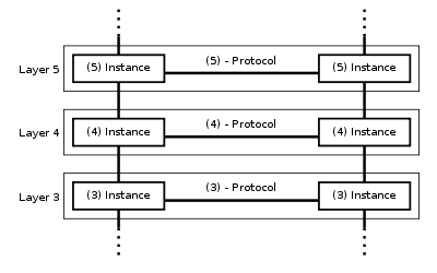 Communication in the OSI-Model (example with layers 3 to 5)
Contents
History
Work on a layered model of network architecture was started and the International Organization for Standardization (ISO) began to develop its OSI framework architecture. OSI had two major components: an abstract model of networking, called the Basic Reference Model or seven-layer model, and a set of specific protocols.
The concept of a seven-layer model was provided by the work of Charles Bachman, Honeywell Information Services. Various aspects of OSI design evolved from experiences with the ARPANET, the fledgling Internet, NPLNET, EIN, CYCLADES network and the work in IFIP WG6.1. The new design was documented in ISO 7498 and its various addenda. In this model, a networking system was divided into layers. Within each layer, one or more entities implement its functionality. Each entity interacted directly only with the layer immediately beneath it, and provided facilities for use by the layer above it.
Protocols enabled an entity in one host to interact with a corresponding entity at the same layer in another host. Service definitions abstractly described the functionality provided to an (N)-layer by an (N-1) layer, where N was one of the seven layers of protocols operating in the local host.
The OSI standards documents are available from the ITU-T as the X.200-series of recommendations.[1] Some of the protocol specifications were also available as part of the ITU-T X series. The equivalent ISO and ISO/IEC standards for the OSI model were available from ISO, but only some of them without fees.[2]
Description of OSI layers
According to recommendation X.200, there are seven layers, each generically known as an N layer. An N+1 entity requests services from the layer-N entity.
At each level, two entities (N-entity peers) interact by means of the N protocol by transmitting protocol data units (PDU).
A Service Data Unit (SDU) is a specific unit of data that has been passed down from an OSI layer to a lower layer, and which the lower layer has not yet encapsulated into a protocol data unit (PDU). An SDU is a set of data that is sent by a user of the services of a given layer, and is transmitted semantically unchanged to a peer service user.
The PDU at any given layer, layer N, is the SDU of the layer below, layer N-1. In effect the SDU is the 'payload' of a given PDU. That is, the process of changing a SDU to a PDU, consists of an encapsulation process, performed by the lower layer. All the data contained in the SDU becomes encapsulated within the PDU. The layer N-1 adds headers or footers, or both, to the SDU, transforming it into a PDU of layer N-1. The added headers or footers are part of the process used to make it possible to get data from a source to a destination.
OSI Model Data unit Layer Function Host
layersData 7. Application Network process to application 6. Presentation Data representation, encryption and decryption, convert machine dependent data to machine independent data 5. Session Interhost communication, managing sessions between applications Segments 4. Transport End-to-end connections, reliability and flow control Media
layersPacket/Datagram 3. Network Path determination and logical addressing Frame 2. Data link Physical addressing Bit 1. Physical Media, signal and binary transmission Some orthogonal aspects, such as management and security, involve every layer.
Security services are not related to a specific layer: they can be related by a number of layers, as defined by ITU-T X.800 Recommendation.[3]
These services are aimed to improve the CIA triad (confidentiality, integrity, and availability) of transmitted data. Actually the availability of communication service is determined by network design and/or network management protocols. Appropriate choices for these are needed to protect against denial of service.
Layer 1: physical layer
The physical layer defines electrical and physical specifications for devices. In particular, it defines the relationship between a device and a transmission medium, such as a copper or optical cable. This includes the layout of pins, voltages, cable specifications, hubs, repeaters, network adapters, host bus adapters (HBA used in storage area networks) and more.
The major functions and services performed by the physical layer are:
- Establishment and termination of a connection to a communications medium.
- Participation in the process whereby the communication resources are effectively shared among multiple users. For example, contention resolution and flow control.
- Modulation, or conversion between the representation of digital data in user equipment and the corresponding signals transmitted over a communications channel. These are signals operating over the physical cabling (such as copper and optical fiber) or over a radio link.
Parallel SCSI buses operate in this layer, although it must be remembered that the logical SCSI protocol is a transport layer protocol that runs over this bus. Various physical-layer Ethernet standards are also in this layer; Ethernet incorporates both this layer and the data link layer. The same applies to other local-area networks, such as token ring, FDDI, ITU-T G.hn and IEEE 802.11, as well as personal area networks such as Bluetooth and IEEE 802.15.4.
Layer 2: data link layer
The data link layer provides the functional and procedural means to transfer data between network entities and to detect and possibly correct errors that may occur in the physical layer. Originally, this layer was intended for point-to-point and point-to-multipoint media, characteristic of wide area media in the telephone system. Local area network architecture, which included broadcast-capable multiaccess media, was developed independently of the ISO work in IEEE Project 802. IEEE work assumed sublayering and management functions not required for WAN use. In modern practice, only error detection, not flow control using sliding window, is present in data link protocols such as Point-to-Point Protocol (PPP), and, on local area networks, the IEEE 802.2 LLC layer is not used for most protocols on the Ethernet, and on other local area networks, its flow control and acknowledgment mechanisms are rarely used. Sliding window flow control and acknowledgment is used at the transport layer by protocols such as TCP, but is still used in niches where X.25 offers performance advantages.
The ITU-T G.hn standard, which provides high-speed local area networking over existing wires (power lines, phone lines and coaxial cables), includes a complete data link layer which provides both error correction and flow control by means of a selective repeat Sliding Window Protocol.
Both WAN and LAN service arrange bits, from the physical layer, into logical sequences called frames. Not all physical layer bits necessarily go into frames, as some of these bits are purely intended for physical layer functions. For example, every fifth bit of the FDDI bit stream is not used by the layer.
WAN protocol architecture
Connection-oriented WAN data link protocols, in addition to framing, detect and may correct errors. They are also capable of controlling the rate of transmission. A WAN data link layer might implement a sliding window flow control and acknowledgment mechanism to provide reliable delivery of frames; that is the case for Synchronous Data Link Control (SDLC) and HDLC, and derivatives of HDLC such as LAPB and LAPD.
IEEE 802 LAN architecture
Practical, connectionless LANs began with the pre-IEEE Ethernet specification, which is the ancestor of IEEE 802.3. This layer manages the interaction of devices with a shared medium, which is the function of a media access control (MAC) sublayer. Above this MAC sublayer is the media-independent IEEE 802.2 Logical Link Control (LLC) sublayer, which deals with addressing and multiplexing on multiaccess media.
While IEEE 802.3 is the dominant wired LAN protocol and IEEE 802.11 the wireless LAN protocol, obsolescent MAC layers include Token Ring and FDDI. The MAC sublayer detects but does not correct errors.
Layer 3: network layer
The network layer provides the functional and procedural means of transferring variable length data sequences from a source host on one network to a destination host on a different network, while maintaining the quality of service requested by the transport layer (in contrast to the data link layer which connects hosts within the same network). The network layer performs network routing functions, and might also perform fragmentation and reassembly, and report delivery errors. Routers operate at this layer, sending data throughout the extended network and making the Internet possible. This is a logical addressing scheme – values are chosen by the network engineer. The addressing scheme is not hierarchical.
The network layer may be divided into three sublayers:
- Subnetwork access – that considers protocols that deal with the interface to networks, such as X.25;
- Subnetwork-dependent convergence – when it is necessary to bring the level of a transit network up to the level of networks on either side
- Subnetwork-independent convergence – handles transfer across multiple networks.
An example of this latter case is CLNP, or IPv7 ISO 8473. It manages the connectionless transfer of data one hop at a time, from end system to ingress router, router to router, and from egress router to destination end system. It is not responsible for reliable delivery to a next hop, but only for the detection of erroneous packets so they may be discarded. In this scheme, IPv4 and IPv6 would have to be classed with X.25 as subnet access protocols because they carry interface addresses rather than node addresses.
A number of layer-management protocols, a function defined in the Management Annex, ISO 7498/4, belong to the network layer. These include routing protocols, multicast group management, network-layer information and error, and network-layer address assignment. It is the function of the payload that makes these belong to the network layer, not the protocol that carries them.
Layer 4: transport layer
The transport layer provides transparent transfer of data between end users, providing reliable data transfer services to the upper layers. The transport layer controls the reliability of a given link through flow control, segmentation/desegmentation, and error control. Some protocols are state- and connection-oriented. This means that the transport layer can keep track of the segments and retransmit those that fail. The transport layer also provides the acknowledgement of the successful data transmission and sends the next data if no errors occurred.
OSI defines five classes of connection-mode transport protocols ranging from class 0 (which is also known as TP0 and provides the least features) to class 4 (TP4, designed for less reliable networks, similar to the Internet). Class 0 contains no error recovery, and was designed for use on network layers that provide error-free connections. Class 4 is closest to TCP, although TCP contains functions, such as the graceful close, which OSI assigns to the session layer. Also, all OSI TP connection-mode protocol classes provide expedited data and preservation of record boundaries. Detailed characteristics of TP0-4 classes are shown in the following table:[4]
Feature Name TP0 TP1 TP2 TP3 TP4 Connection oriented network Yes Yes Yes Yes Yes Connectionless network No No No No Yes Concatenation and separation No Yes Yes Yes Yes Segmentation and reassembly Yes Yes Yes Yes Yes Error Recovery No Yes Yes Yes Yes Reinitiate connection (if an excessive number of PDUs are unacknowledged) No Yes No Yes No Multiplexing and demultiplexing over a single virtual circuit No No Yes Yes Yes Explicit flow control No No Yes Yes Yes Retransmission on timeout No No No No Yes Reliable Transport Service No Yes No Yes Yes Perhaps an easy way to visualize the transport layer is to compare it with a Post Office, which deals with the dispatch and classification of mail and parcels sent. Do remember, however, that a post office manages the outer envelope of mail. Higher layers may have the equivalent of double envelopes, such as cryptographic presentation services that can be read by the addressee only. Roughly speaking, tunneling protocols operate at the transport layer, such as carrying non-IP protocols such as IBM's SNA or Novell's IPX over an IP network, or end-to-end encryption with IPsec. While Generic Routing Encapsulation (GRE) might seem to be a network-layer protocol, if the encapsulation of the payload takes place only at endpoint, GRE becomes closer to a transport protocol that uses IP headers but contains complete frames or packets to deliver to an endpoint. L2TP carries PPP frames inside transport packet.
Although not developed under the OSI Reference Model and not strictly conforming to the OSI definition of the transport layer, the Transmission Control Protocol (TCP) and the User Datagram Protocol (UDP) of the Internet Protocol Suite are commonly categorized as layer-4 protocols within OSI.
Layer 5: session layer
The session layer controls the dialogues (connections) between computers. It establishes, manages and terminates the connections between the local and remote application. It provides for full-duplex, half-duplex, or simplex operation, and establishes checkpointing, adjournment, termination, and restart procedures. The OSI model made this layer responsible for graceful close of sessions, which is a property of the Transmission Control Protocol, and also for session checkpointing and recovery, which is not usually used in the Internet Protocol Suite. The session layer is commonly implemented explicitly in application environments that use remote procedure calls.
Layer 6: presentation layer
The presentation layer establishes context between application-layer entities, in which the higher-layer entities may use different syntax and semantics if the presentation service provides a mapping between them. If a mapping is available, presentation service data units are encapsulated into session protocol data units, and passed down the stack.
This layer provides independence from data representation (e.g., encryption) by translating between application and network formats. The presentation layer transforms data into the form that the application accepts. This layer formats and encrypts data to be sent across a network. It is sometimes called the syntax layer.[5]
The original presentation structure used the basic encoding rules of Abstract Syntax Notation One (ASN.1), with capabilities such as converting an EBCDIC-coded text file to an ASCII-coded file, or serialization of objects and other data structures from and to XML.
Layer 7: application layer
The application layer is the OSI layer closest to the end user, which means that both the OSI application layer and the user interact directly with the software application. This layer interacts with software applications that implement a communicating component. Such application programs fall outside the scope of the OSI model. Application-layer functions typically include identifying communication partners, determining resource availability, and synchronizing communication. When identifying communication partners, the application layer determines the identity and availability of communication partners for an application with data to transmit. When determining resource availability, the application layer must decide whether sufficient network or the requested communication exist. In synchronizing communication, all communication between applications requires cooperation that is managed by the application layer. Some examples of application-layer implementations also include:
- On OSI stack:
- FTAM File Transfer and Access Management Protocol
- X.400 Mail
- Common management information protocol (CMIP)
- On TCP/IP stack:
- Hypertext Transfer Protocol (HTTP),
- File Transfer Protocol (FTP),
- Simple Mail Transfer Protocol (SMTP)
- Simple Network Management Protocol (SNMP).
Cross-layer functions
There are some functions or services that are not tied to a given layer, but they can affect more than one layer. Examples are
- security service (telecommunication)[3] as defined by ITU-T X.800 Recommendation.
- management functions, i.e. functions that permit to configure, instantiate, monitor, terminate the communications of two or more entities: there is a specific application layer protocol, common management information protocol (CMIP) and its corresponding service, common management information service (CMIS), they need to interact with every layer in order to deal with their instances.
- MPLS operates at an OSI-model layer that is generally considered to lie between traditional definitions of layer 2 (data link layer) and layer 3 (network layer), and thus is often referred to as a "layer-2.5" protocol. It was designed to provide a unified data-carrying service for both circuit-based clients and packet-switching clients which provide a datagram service model. It can be used to carry many different kinds of traffic, including IP packets, as well as native ATM, SONET, and Ethernet frames.
- ARP is used to translate IPv4 addresses (OSI layer 3) into Ethernet MAC addresses (OSI layer 2).
Interfaces
Neither the OSI Reference Model nor OSI protocols specify any programming interfaces, other than as deliberately abstract service specifications. Protocol specifications precisely define the interfaces between different computers, but the software interfaces inside computers are implementation-specific.
For example Microsoft Windows' Winsock, and Unix's Berkeley sockets and System V Transport Layer Interface, are interfaces between applications (layer 5 and above) and the transport (layer 4). NDIS and ODI are interfaces between the media (layer 2) and the network protocol (layer 3).
Interface standards, except for the physical layer to media, are approximate implementations of OSI service specifications.
Examples
Layer OSI protocols TCP/IP protocols Signaling System 7[6] AppleTalk IPX SNA UMTS Misc. examples # Name 7 Application FTAM, X.400, X.500, DAP, ROSE, RTSE, ACSE[7] CMIP[8] NNTP, SIP, SSI, DNS, FTP, Gopher, HTTP, NFS, NTP, DHCP, SMPP, SMTP, SNMP, Telnet, RIP, BGP INAP, MAP, TCAP, ISUP, TUP AFP, ZIP, RTMP, NBP RIP, SAP APPC HL7, Modbus 6 Presentation ISO/IEC 8823, X.226, ISO/IEC 9576-1, X.236 MIME, SSL, TLS, XDR AFP TDI, ASCII, EBCDIC, MIDI, MPEG 5 Session ISO/IEC 8327, X.225, ISO/IEC 9548-1, X.235 Sockets. Session establishment in TCP, RTP ASP, ADSP, PAP NWLink DLC? Named pipes, NetBIOS, SAP, half duplex, full duplex, simplex, RPC 4 Transport ISO/IEC 8073, TP0, TP1, TP2, TP3, TP4 (X.224), ISO/IEC 8602, X.234 TCP, UDP, SCTP, DCCP DDP, SPX NBF 3 Network ISO/IEC 8208, X.25 (PLP), ISO/IEC 8878, X.223, ISO/IEC 8473-1, CLNP X.233. IP, IPsec, ICMP, IGMP, OSPF SCCP, MTP ATP (TokenTalk or EtherTalk) IPX RRC (Radio Resource Control) Packet Data Convergence Protocol (PDCP) and BMC (Broadcast/Multicast Control) NBF, Q.931, IS-IS 2 Data Link ISO/IEC 7666, X.25 (LAPB), Token Bus, X.222, ISO/IEC 8802-2 LLC Type 1 and 2[9] PPP, SBTV SLIP, PPTP MTP, Q.710 LocalTalk, AppleTalk Remote Access, PPP IEEE 802.3 framing, Ethernet II framing SDLC LLC (Logical Link Control), MAC (Media Access Control) 802.3 (Ethernet), 802.11a/b/g/n MAC/LLC, 802.1Q (VLAN), ATM, HDP, FDDI, Fibre Channel, Frame Relay, HDLC, ISL, PPP, Q.921, Token Ring, CDP, NDP ARP (maps layer 3 to layer 2 address), ITU-T G.hn DLL
CRC, Bit stuffing, ARQ, Data Over Cable Service Interface Specification (DOCSIS), interface bonding1 Physical X.25 (X.21bis, EIA/TIA-232, EIA/TIA-449, EIA-530, G.703)[9] MTP, Q.710 RS-232, RS-422, STP, PhoneNet Twinax UMTS Physical layer or L1 RS-232, Full duplex, RJ45, V.35, V.34, I.430, I.431, T1, E1, 10BASE-T, 100BASE-TX, POTS, SONET, SDH, DSL, 802.11a/b/g/n PHY, ITU-T G.hn PHY, Controller Area Network, Data Over Cable Service Interface Specification (DOCSIS) Comparison with TCP/IP
In the TCP/IP model of the Internet, protocols are deliberately not as rigidly designed into strict layers as in the OSI model.[10] RFC 3439 contains a section entitled "Layering considered harmful." However, TCP/IP does recognize four broad layers of functionality which are derived from the operating scope of their contained protocols, namely the scope of the software application, the end-to-end transport connection, the internetworking range, and lastly the scope of the direct links to other nodes on the local network.
Even though the concept is different from the OSI model, these layers are nevertheless often compared with the OSI layering scheme in the following way: The Internet application layer includes the OSI application layer, presentation layer, and most of the session layer. Its end-to-end transport layer includes the graceful close function of the OSI session layer as well as the OSI transport layer. The internetworking layer (Internet layer) is a subset of the OSI network layer (see above), while the link layer includes the OSI data link and physical layers, as well as parts of OSI's network layer. These comparisons are based on the original seven-layer protocol model as defined in ISO 7498, rather than refinements in such things as the internal organization of the network layer document.
The presumably strict peer layering of the OSI model as it is usually described does not present contradictions in TCP/IP, as it is permissible that protocol usage does not follow the hierarchy implied in a layered model. Such examples exist in some routing protocols (e.g., OSPF), or in the description of tunneling protocols, which provide a link layer for an application, although the tunnel host protocol may well be a transport or even an application layer protocol in its own right.
See also
- Cognitive networks
- Hierarchical internetworking model
- Internet protocol suite
- Layer 8
- OSI protocol suite
- Protocol stack
- Service layer
- TCP/IP model
- X.25 protocol suite
- WAP protocol suite
- List of information technology acronyms
References
- ^ ITU-T X-Series Recommendations
- ^ "Publicly Available Standards". Standards.iso.org. 2010-07-30. http://standards.iso.org/ittf/PubliclyAvailableStandards/index.html. Retrieved 2010-09-11.
- ^ a b X.800 : Security architecture for Open Systems Interconnection for CCITT applications
- ^ "ITU-T Recommendation X.224 (11/1995) ISO/IEC 8073". http://www.itu.int/rec/T-REC-X.224-199511-I/en/.
- ^ Grigonis, Richard (2000). Computer telephony encyclopedia. CMP. pp. 331. http://books.google.com/books?id=cUYk0ZhOxpEC&printsec=frontcover&dq=computer+telephony+encyclopedia&ct=result#v=onepage&q&f=false.
- ^ ITU-T Recommendation Q.1400 (03/1993), Architecture framework for the development of signaling and OA&M protocols using OSI concepts, pp 4, 7.
- ^ ITU Rec. X.227 (ISO 8650), X.217 (ISO 8649)
- ^ X.700 series of recommendations from the ITU-T (in particular X.711), and ISO 9596
- ^ a b CISCO Cisco Systems, Inc. Internetworking Technology Handbook OSI Model Physical layer
- ^ RFC 3439
External links
- ISO/IEC standard 7498-1:1994 (PDF document inside ZIP archive) (requires HTTP cookies in order to accept licence agreement)
- ITU-T X.200 (the same contents as from ISO)
- The ISO OSI Reference Model , Beluga graph of data units and groups of layers
- OSI Reference Model — The ISO Model of Architecture for Open Systems InterconnectionPDF (776 KB), Hubert Zimmermann, IEEE Transactions on Communications, vol. 28, no. 4, April 1980, pp. 425 – 432.
- Cisco Systems Internetworking Technology Handbook
ISO standards Lists: List of ISO standards · List of ISO romanizations · List of IEC standards
Categories: Category:ISO standards · Category:OSI protocols1
to
99991 · 2 · 3 · 4 · 5 · 6 · 7 · 9 · 16 · 31 (-0, -1, -2, -3, -4, -5, -6, -7, -8, -9, -10, -11, -12, -13) · 128 · 216 · 217 · 226 · 228 · 233 · 259 · 269 · 302 · 306 · 428 · 518 · 519 · 639 (-1, -2, -3, -5, -6) · 646 · 690 · 732 · 764 · 843 · 898 · 1000 · 1004 · 1007 · 1073-1 · 1413 · 1538 · 1745 · 2014 · 2015 · 2022 · 2108 · 2145 · 2146 · 2240 · 2281 · 2709 · 2711 · 2788 · 3029 · 3103 · 3166 (-1, -2, -3) · 3297 · 3307 · 3602 · 3864 · 3901 · 3977 · 4031 · 4157 · 4217 · 5218 · 5775 · 5776 · 5800 · 5964 · 6166 · 6344 · 6346 · 6425 · 6429 · 6438 · 6523 · 6709 · 7001 · 7002 · 7098 · 7185 · 7200 · 7498 · 7736 · 7810 · 7811 · 7812 · 7813 · 7816 · 8000 · 8178 · 8217 · 8571 · 8583 · 8601 · 8632 · 8652 · 8691 · 8807 · 8820-5 · 8859 (-1, -2, -3, -4, -5, -6, -7, -8, -9, -10, -11, -12, -13, -14, -15, -16) · 8879 · 9000/9001 · 9075 · 9126 · 9241 · 9362 · 9407 · 9506 · 9529 · 9564 · 9594 · 9660 · 9897 · 9945 · 9984 · 9985 · 999510000
to
1999910006 · 10118-3 · 10160 · 10161 · 10165 · 10179 · 10206 · 10303 (-11, -21, -22, -28, -238) · 10383 · 10487 · 10585 · 10589 · 10646 · 10664 · 10746 · 10861 · 10957 · 10962 · 10967 · 11073 · 11170 · 11179 · 11404 · 11544 · 11783 · 11784 · 11785 · 11801 · 11898 · 11940 · 11941 · 11941 (TR) · 11992 · 12006 · 12182:1998 · 12207 · 12234-2 · 13211 (-1, -2) · 13216 · 13250 · 13399 · 13406-2 · 13407 · 13450 · 13485 · 13490 · 13567 · 13568 · 13584 · 13616 · 14000 · 14031 · 14396 · 14443 · 14496-10 · 14496-14 · 14644 (-1, -2, -3, -4, -5, -6, -7, -8, -9) · 14649 · 14651 · 14698 · 14698-2 · 14750 · 14882 · 14971 · 15022 · 15189 · 15288 · 15291 · 15292 · 15408 · 15444 · 15445 · 15438 · 15504 · 15511 · 15686 · 15693 · 15706 · 15706-2 · 15707 · 15897 · 15919 · 15924 · 15926 · 15926 WIP · 15930 · 16023 · 16262 · 16750 · 17024 · 17025 · 17369 · 17799 · 18000 · 18004 · 18014 · 18245 · 18629 · 18916 · 19005 · 19011 · 19092-1 · 19092-2 · 19114 · 19115 · 19125 · 19136 · 19439 · 19501:2005 · 19752 · 19757 · 19770 · 19775-1 · 19794-520000+ See also: All articles beginning with "ISO"Categories:- ISO standards
- ITU-T recommendations
- Network architecture
- OSI protocols
- Reference models
- Computer networking

Wikimedia Foundation. 2010.