- Cavity magnetron
-
 Magnetron with section removed (magnet is not shown)
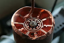 A similar magnetron with a different section removed (magnet is not shown).
The cavity magnetron is a high-powered vacuum tube that generates microwaves using the interaction of a stream of electrons with a magnetic field. The 'resonant' cavity magnetron variant of the earlier magnetron tube was invented by John Randall and Harry Boot in 1940 at the University of Birmingham, England.[1] The high power of pulses from the cavity magnetron made centimeter-band radar practical. Shorter wavelength radars allowed detection of smaller objects. The compact cavity magnetron tube drastically reduced the size of radar sets[2] so that they could be installed in anti-submarine aircraft[3] and escort ships.[2] At present, cavity magnetrons are commonly used in microwave ovens and in various radar applications.[4]
Contents
Construction and operation
All cavity magnetrons consist of a hot cathode with a high (continuous or pulsed) negative potential by a high-voltage, direct-current power supply. The cathode is built into the center of an evacuated, lobed, circular chamber. A magnetic field parallel to the filament is imposed by a permanent magnet. The magnetic field causes the electrons, attracted to the (relatively) positive outer part of the chamber, to spiral outward in a circular path rather than moving directly to this anode. Spaced around the rim of the chamber are cylindrical cavities. The cavities are open along their length and connect the common cavity space. These cavities act just like very highly efficient tuned circuits. As electrons sweep past these openings, they induce a resonant, high-frequency radio field in the cavity, which in turn causes the electrons to bunch into groups. The principle is very similar to blowing a stream of air across the open top of a glass pop bottle. The cavities resonate, and emit a powerful radio-frequency energy output. A portion of this field is extracted with a short antenna that is connected to a waveguide (a metal tube usually of rectangular cross section). The waveguide directs the extracted RF energy to the load, which may be a cooking chamber in a microwave oven or a high-gain antenna in the case of radar.
 A cross-sectional diagram of a resonant cavity magnetron. Magnetic lines of force are parallel to the geometric axis of this structure.
The sizes of the cavities determine the resonant frequency, and thereby the frequency of emitted microwaves. However, the frequency is not precisely controllable. The operating frequency varies with changes in load impedance, with changes in the supply current, and with the temperature of the tube.[5] This is not a problem in uses such as heating, or in some forms of radar where the receiver can be synchronized with an imprecise magnetron frequency. Where precise frequencies are needed, other devices such as the klystron are used.
The magnetron is a self-oscillating device requiring no external elements other than a power supply. A well-defined threshold anode voltage must be applied before oscillation will build up; this voltage is a function of the dimensions of the resonant cavity, and the applied magnetic field. In pulsed applications there is a delay of several cycles before the oscillator achieves full peak power, and the build-up of anode voltage must be coordinated with the build-up of oscillator output.[5]
The magnetron is a fairly efficient device. In a microwave oven, for instance, a 1.1 kilowatt input will generally create about 700 watt of microwave power, an efficiency of around 65%. (The high-voltage and the properties of the cathode determine the power of a magnetron.) Large S-band magnetrons can produce up to 2.5 megawatts peak power with an average power of 3.75 kW.[5] Large magnetrons can be water cooled. The magnetron remains in widespread use in roles which require high power, but where precise frequency control is unimportant.
Applications
 Magnetron from a microwave oven with magnet in its mounting box. The horizontal plates form a heat sink, cooled by airflow from a fan
Radar
Main article: History of radar (Centimetric radar)In radar devices, the waveguide is connected to an antenna. The magnetron is operated with very short pulses of applied voltage, resulting in a short pulse of high power microwave energy being radiated. As in all radar systems, the radiation reflected off a target is analyzed to produce a radar map on a screen.
Several characteristics of the magnetron's power output conspire to make radar use of the device somewhat problematic. The first of these factors is the magnetron's inherent instability in its transmitter frequency. This instability is noted not only as a frequency shift from one pulse to the next, but also a frequency shift within an individual transmitter pulse. The second factor is that the energy of the transmitted pulse is spread over a wide frequency spectrum, which makes necessary its receiver to have a corresponding wide selectivity. This wide selectivity permits ambient electrical noise to be accepted into the receiver, thus obscuring somewhat the received radar echoes, thereby reducing overall radar performance. The third factor, depending on application, is the radiation hazard caused by the use of high power electromagnetic radiation. In some applications, for example a marine radar mounted on a recreational vessel, a radar with a magnetron output of 2 to 4 kilowatts is often found mounted very near an area occupied by crew or passengers. In practical use, these factors have been overcome, or merely accepted, and there are today thousands of magnetron aviation and marine radar units in service. Recent advances in aviation weather avoidance radar and in marine radar have successfully implemented semiconductor transmitters that eliminate the magnetron entirely.
Heating
In microwave ovens, the waveguide leads to a radio frequency-transparent port into the cooking chamber.
Lighting
In microwave-excited lighting systems, such as a sulfur lamp, a magnetron provides the microwave field that is passed through a waveguide to the lighting cavity containing the light-emitting substance (e.g., sulfur, metal halides, etc.)
History
The first simple, two-pole magnetron was developed in 1920 by Albert Hull[6] at General Electric's Research Laboratories (Schenectady, New York), as an outgrowth of his work on the magnetic control of vacuum tubes in an attempt to work around the patents held by Lee De Forest on electrostatic control.
Hull's magnetron was not originally intended to generate VHF (very-high-frequency) electromagnetic waves. However, in 1924, Czech physicist August Žáček[7] (1886–1961) and German physicist Erich Habann[8] (1892–1968) independently discovered that the magnetron could generate waves of 100 megahertz to 1 gigahertz. Žáček, a professor at Prague's Charles University, published first; however, he published in a journal with a small circulation and thus attracted little attention.[9] Habann, a student at the University of Jena, investigated the magnetron for his doctoral dissertation of 1924.[10] Throughout the 1920s, Hull and other researchers around the world worked to develop the magnetron.[11][12][13] Most of these early magnetrons were glass vacuum tubes with multiple anodes. However, the two-pole magnetron, also known as a split-anode magnetron, had relatively low efficiency. The cavity version (properly referred to as a resonant-cavity magnetron) proved to be far more useful. An early multi-cavity version of the magnetron was reported by Bucharest University Professor Theodor V. Ionescu. and followed in 1937-1940 by a similar multi-cavity magnetron built by the British physicist, Sir John Turton Randall, FRSE together with a team of British coworkers for the British and American, military radar installations in WWII.[14]
While radar was being developed during World War II, there arose an urgent need for a high-power microwave generator that worked at shorter wavelengths (around 10 cm (3 GHz)) rather than the 150 cm (200 MHz) that was available from tube-based generators of the time. It was known that a multi-cavity resonant magnetron had been developed and patented in 1935 by Hans Hollmann in Berlin,[15] and independently, in 1935, by physicist Theodor V. Ionescu in Romania. However, the German military considered the frequency drift of Hollman's device to be undesirable, and based their radar systems on the klystron instead. But klystrons could not achieve the high power output that magnetrons eventually reached. This was one reason that German night fighter radars were not a match for their British counterparts.[16]
 Original Randall and Boot cavity magnetron
In 1940, at the University of Birmingham in the United Kingdom, John Randall and Harry Boot produced a working prototype similar to Hollman's cavity magnetron, but added liquid cooling and a stronger cavity. Randall and Boot soon managed to increase its power output 100 fold. Instead of abandoning the magnetron due to its frequency instability, they sampled the output signal and synchronized their receiver to whatever frequency was actually being generated. In 1941, the problem of frequency instability was solved by coupling alternate cavities within the magnetron.
Because France had just fallen to the Nazis and Britain had no money to develop the magnetron on a massive scale, Churchill agreed that Sir Henry Tizard should offer the magnetron to the Americans in exchange for their financial and industrial help (the Tizard Mission). An early 6 kW version, built in England by the General Electric Company Research Laboratories, Wembley, London (not to be confused with the similarly named American company General Electric), was given to the US government in September 1940. At the time the most powerful equivalent microwave producer available in the US (a klystron) had a power of only ten watts. The cavity magnetron was widely used during World War II in microwave radar equipment and is often credited with giving Allied radar a considerable performance advantage over German and Japanese radars, thus directly influencing the outcome of the war. It was later described as "the most valuable cargo ever brought to our shores".[17]
The Bell Telephone Laboratories made a producible version from the magnetron delivered to America by the Tizard Mission, and before the end of 1940, the Radiation Laboratory had been set up on the campus of the Massachusetts Institute of Technology to develop various types of radar using the magnetron. By early 1941, portable centimetric airborne radars were being tested in American and British planes.[18] In late 1941, the Telecommunications Research Establishment in Great Britain used the magnetron to develop a revolutionary airborne, ground-mapping radar codenamed H2S. The H2S radar was in part developed by Alan Blumlein and Bernard Lovell.
Centimetric radar, made possible by the cavity magnetron, allowed for the detection of much smaller objects and the use of much smaller antennas. The combination of small-cavity magnetrons, small antennas, and high resolution allowed small, high quality radars to be installed in aircraft. They could be used by maritime patrol aircraft to detect objects as small as a submarine periscope, which allowed aircraft to attack and destroy submerged submarines which had previously been undetectable from the air. Centimetric contour mapping radars like H2S improved the accuracy of Allied bombers used in the strategic bombing campaign. Centimetric gun-laying radars were likewise far more accurate than the older technology. They made the big-gunned Allied battleships more deadly and, along with the newly developed proximity fuze, made anti-aircraft guns much more dangerous to attacking aircraft. The two coupled together and used by anti-aircraft batteries, placed along the flight path of German V-1 flying bombs on their way to London, are credited with destroying many of the flying bombs before they reached their target.
Since then, many millions of cavity magnetrons have been manufactured; while some have been for radar the vast majority have been for microwave ovens. The use in radar itself has dwindled to some extent, as more accurate signals have generally been needed and developers have moved to klystron and traveling-wave tube systems for these needs.
Health hazards
 Caution: radiowaves hazard
Among more speculative hazards, at least one in particular is well known and documented. As the lens of the eye has no cooling blood flow, it is particularly prone to overheating when exposed to microwave radiation. This heating can in turn lead to a higher incidence of cataracts in later life.[19] A microwave oven with a warped door or poor microwave sealing can be hazardous.
There is also a considerable electrical hazard around magnetrons, as they require a high voltage power supply.
Some magnetrons have beryllium oxide (beryllia) ceramic insulators, which are dangerous if crushed and inhaled, or otherwise ingested. Single or chronic exposure can lead to berylliosis, an incurable lung condition. In addition, beryllia is listed as a confirmed human carcinogen by the IARC; therefore, broken ceramic insulators or magnetrons should not be directly handled.
See also
- Cyclotron – An atomic accelerator that also directs particles in a spiral with a transverse magnetic field.
- Klystron – A device for amplifying or generating microwaves with greater precision and control than is available from the magnetron.
- Traveling-wave tube – Another microwave amplifier device, capable of greater bandwidths than a klystron.
- Crossed-field amplifier – A device combining characteristics of magnetrons and TWTs, resulting in a high-powered, narrow-band amplifier.
- Backward wave oscillator - A wide-band tunable oscillator, M or O-type
- Free-electron laser – A device for amplifying or generating microwaves, infrared light, UV, and X-Rays.
- Maser – A device for generating microwaves that produces a very low noise and stable signal, a predecessor of the laser.
- Laser – A device for generating coherent light, an evolution of the maser.
- Sputter deposition – An important industrial application using the same principle of crossed electric and magnetic fields as cavity balls.
- Radar
- H2S radar
- Rad Lab
- Sir John Turton Randall, FRSE
- Theodor V. Ionescu
- Hans Hollmann
- Harry Boot
- Albert Hull
- Alan Blumlein
- Bernard Lovell
References
- ^ "The Magnetron". Bournemouth University. 1995-2009. http://histru.bournemouth.ac.uk/Oral_History/Talking_About_Technology/radar_research/the_magnetron.html. Retrieved 23 August 2009.
- ^ a b Schroter, B. (Spring 2008). "How important was Tizard’s Box of Tricks?". Imperial Engineer 8: 10. http://www3.imperial.ac.uk/pls/portallive/docs/1/44009701.PDF. Retrieved 2009-08-23.
- ^ "Who Was Alan Dower Blumlein?". Dora Media Productions. 1999-2007. http://www.doramusic.com/Who%20Was%20Blumlein.htm. Retrieved 23 August 2009.
- ^ Ma, L. "3D Computer Modeling of Magnetrons." University of London Ph.D. Thesis. December 2004. Accessed 2009-08-23.
- ^ a b c L.W. Turner,(ed), Electronics Engineer's Reference Book, 4th ed. Newnes-Butterworth, London 1976 ISBN 0 408 00168, pages 7-71 to 7-77
- ^ Albert W. Hull, "The effect of a uniform magnetic field on the motion of electrons between coaxial cylinders," Physical Review, vol. 18, no. 1, pages 31-57 (1921). See also: Albert W. Hull, "The magnetron," Journal of the American Institute of Electrical Engineers, vol. 40, no. 9, pages 715-723 (September 1921).
- ^ Biographical information about August Žáček: (1) R. H. Fürth, Obituary: "Prof. August Žáček," Nature, vol. 193, no. 4816, page 625 (1962); and (2) "The 70th birthday of Prof. Dr. August Žáček," Czechoslovak Journal of Physics, vol. 6, no. 2, pages 204-205 (1956). (For ref. (2), see: http://resources.metapress.com/pdf-preview.axd?code=h05r1105157t7x38&size=largest .)
- ^ Biographical information about Erich Habann: Günter Nagel, "Pionier der Funktechnik. Das Lebenswerk des Wissenschaftlers Erich Habann, der in Hessenwinkel lebte, ist heute fast vergessen" (Pioneer in Radio Technology. The life's work of scientist Erich Habann, who lived in Hessenwinkel, is nearly forgotten today.), Bradenburger Blätter (supplement of the Märkische Oderzeitung, a daily newspaper of the city of Frankfurt in the state of Brandenburg, Germany), 15 December 2006, page 9. See also: Rainer Karlsch and Heiko Petermann, ed.s, Für und Wider "Hitlers Bombe": Studien zur Atomforschung in Deutschland [For and Against "Hitler's Bomb": Studies on atomic research in Germany] (N.Y., N.Y.: Waxmann Publishing Co., 2007), page 251 footnote.
- ^ A. Žáček, "Nová metoda k vytvorení netlumenych oscilací" ["New method of generating undamped oscillations"], Časopis pro pěstování matematiky a fysiky [Journal for the Cultivation of Mathematics and Physics], vol. 53, pages 378-380 (May 1924). (Available on-line (in Czech) at: http://dml.cz/bitstream/handle/10338.dmlcz/121857/CasPestMatFys_053-1924-3_4.pdf .) See also: A. Žáček, "Über eine Methode zur Erzeugung von sehr kurzen elektromagnetischen Wellen" [On a method for generating very short electromagnetic waves], Zeitschrift für Hochfrequenztechnik [Journal for High Frequency Technology], vol. 32, pages 172-180 (1928). A. Žáček, "Spojení pro výrobu elektrických vln" ["Circuit for production of electrical waves"], Czechoslovak patent no. 20,293 (filed: 31 May 1924; issued: 15 February 1926). Available on-line (in Czech): http://spisy.upv.cz/Patents/FirstPages/FPPV0020/0020293.pdf .
- ^ Erich Habann, "Eine neue Generatorröhre" [A new generator tube], Zeitschrift für Hochfrequenztechnik, vol. 24, pages 115-120 and 135-141 (1924)
- ^ W. Kaiser, "The Development of Electron Tubes and of Radar technology: The Relationship of Science and Technology," pp. 217 - 236 in O. Blumtritt, H. Petzold and W. Aspray, eds., Tracking the History of Radar, IEEE, Piscataway, NJ, USA, 1994
- ^ James E. Brittain, "The magnetron and the beginnings of the microwave age," Physics Today, vol. 38, pages 60-67 (1985).
- ^ See for example: (1) Soviet physicists: (i) Abram A. Slutskin and Dmitry S. Shteinberg, ["Obtaining oscillations in cathode tubes with the aid of a magnetic field"], Zhurnal Russkogo Fiziko-Khimicheskogo Obshchestva [Journal of the Russian Physico-Chemical Society], vol. 58, no. 2, pages 395-407 (1926); (ii) Abram A. Slutskin and Dmitry S. Shteinberg, ["Electronic oscillations in two-electrode tubes"], Ukrainski Fizychni Zapysky [Ukrainian Journal of Physics], vol. 1, no. 2, pages 22-27 (1927); (iii) A. A. Slutzkin and D. S. Steinberg, "Die Erzeugung von kurzwelligen ungedämpften Schwingungen bei Anwendung des Magnetfeldes" ["The generation of undamped shortwave oscillations by application of a magnetic field"], Annalen der Physik, vol. 393, no. 5, pages 658-670 (May 1929).
(2) Japanese engineers: Hidetsugu Yagi, "Beam transmission of ultra-short waves," Proceedings of the Institute of Radio Engineers, vol. 16, no. 6, pages 715-741 (1928). Magnetrons are discussed in Part II of this article. See also: (i) Kinjiro Okabe, ["Production of intense extra-short radio waves by a split-anode magnetron (Part 3)"], Journal of the Institute of Electrical Engineering of Japan, pages 284ff (March 1928); (ii) Kinjiro Okabe, "On the short-wave limit of magnetron oscillations," Proceedings of the Institute of Radio Engineers, vol. 17, no. 4, pages 652-659 (1929); (iii) Kinjiro Okabe, "On the magnetron oscillation of new type," Proceedings of the Institute of Radio Engineers, vol. 18, no. 10, pages 1748-1749 (1930). - ^ "Radar Recollections - A Bournemouth University/CHiDE/HLF project" by a similar multi-cavity magnetron built by Prof. W. E. Burcham
- ^ US 2123728 Hans Erich Hollmann/Telefunken GmbH: „Magnetron“ filed November 27, 1935
- ^ W. Kaiser, "The Development of Electron Tubes and of Radar technology: The Relationship of Science and Technology," pp. 217 - 236 in O. Blumtritt, H. Petzold and W. Aspray, eds., Tracking the History of Radar, IEEE, Piscataway, NJ, USA, 1994:229
- ^ James Phinney Baxter III (Official Historian of the Office of Scientific Research and Development), Scientists Against Time (Boston: Little, Brown, and Co., 1946), page 142.
- ^ Angela Hind (February 5, 2007). "Briefcase 'that changed the world'". BBC News. http://news.bbc.co.uk/1/hi/sci/tech/6331897.stm. Retrieved 2007-08-16.
- ^ Lipman, R. M.; B. J. Tripathi, R. C. Tripathi (1988). "Cataracts induced by microwave and ionizing radiation". Survey of Ophthalmology 33 (3): 200–210. doi:10.1016/0039-6257(88)90088-4. OSTI 6071133. PMID 3068822.
External links
- Information
- Magnetrons
- Magnetron collection in the Virtual Valve Museum
- MicrowaveCam.com Videos of plasmoids created in a microwave oven
- TMD Magnetrons Information and PDF Data Sheets
- (Title is somewhat cryptic) Concise, notably-excellent article about magnetrons; Fig. 13 is representative of a modern radar magnetron.
- Patents
- US 2123728 Hans Erich Hollmann/Telefunken GmbH: „Magnetron“ filed November 27, 1935
- US 2315313 Buchholz, H. (1943). Cavity resonator
- US 2357313 Carter, P.S. (1944). High frequency resonator and circuit therefor
- US 2357314 Carter, P.S. (1944). Cavity resonator circuit
- US 2408236 Spencer, P.L. (1946). Magnetron casing
- US 2444152 Carter, P.S. (1948). Cavity resonator circuit
- US 2611094 Rex, H.B. (1952). Inductance-capacitance resonance circuit
- GB 879677 Dexter, S.A. (1959). Valve oscillator circuits; radio frequency output couplings
Electronic components Semiconductors Avalanche diode • Barretter • Darlington transistor • DIAC • Diode • Field-effect transistor (FET) • Insulated-gate bipolar transistor (IGBT) • JFET • Light-emitting diode (LED) • Memristor • MOSFET • Photodetector • PIN diode • Silicon-controlled rectifier (SCR) • Thyristor • Transistor • TRIAC • Unijunction transistor (UJT) • Zener diodeVacuum tubes Vacuum tubes (RF) Backward wave oscillator (BWO) • Cavity magnetron • Crossed-field amplifier • Gyrotron • Inductive output tube (IOT) • Klystron • Maser • Traveling-wave tubeAdjustable Passive Connector (Electrical power, Baseband, RF) • Ferrite • Fuse • Resettable fuse • Resistor (Thermistor) • TransformerReactive Categories:- Electrical components
- English inventions
- Microwave technology
- Radar
- Vacuum tubes
- World War II American electronics
- World War II British electronics


Wikimedia Foundation. 2010.