- Television antenna
-
 A Winegard HD-7084P 68 element VHF/UHF aerial antenna
A television antenna, or TV aerial, is an antenna specifically designed for the reception of over the air broadcast television signals, which are transmitted at frequencies from about 41 to 250 MHz in the VHF band, and 470 to 960 MHz in the UHF band in different countries. To cover this range antennas generally consist of multiple conductors of different lengths which correspond to the wavelength range the antenna is intended to receive. The length of the elements of a TV antenna are usually half the wavelength of the signal they are intended to receive. The wavelength of a signal equals the speed of light (c) divided by the frequency. The design of a television broadcast receiving antenna is the same for the older analog transmissions and the digital television (DTV) transmissions which are replacing them. Sellers often claim to supply a special "digital" or "high-definition television" (HDTV) antenna advised as a replacement for an existing analog television antenna, even if satisfactory: this is misinformation to generate sales of unneeded equipment.[1][2]
Television antennas are used in conjunction with a tuner (television) that are included with television sets.
Contents
Simple/indoor
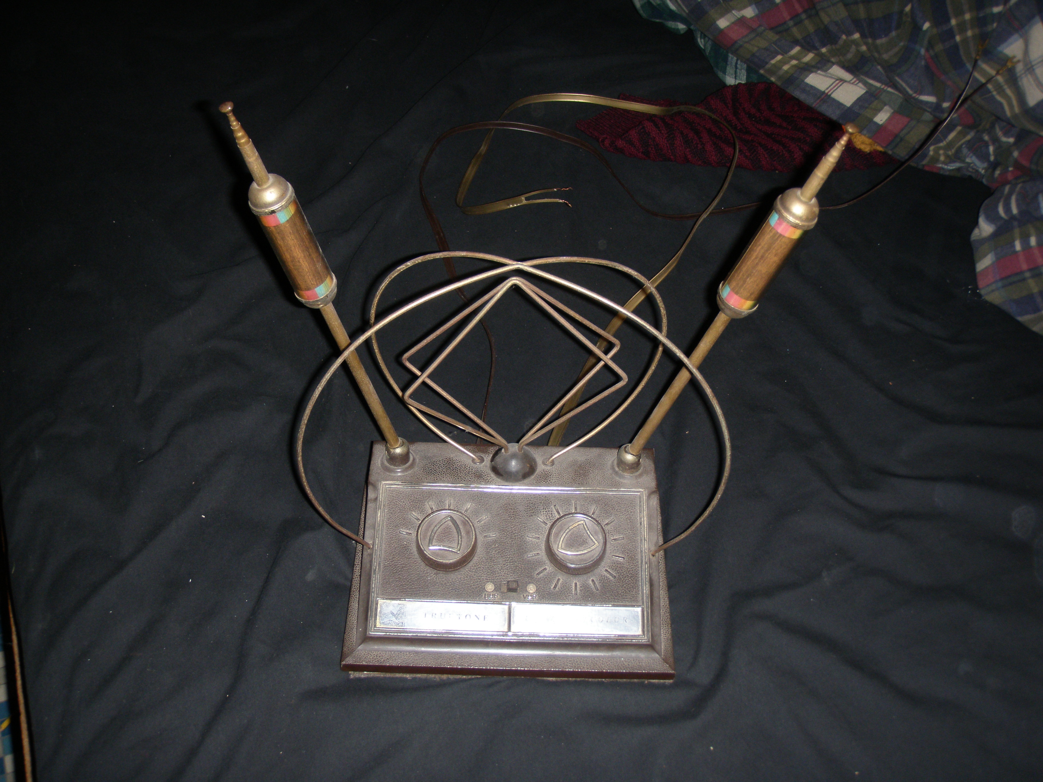
 Very common "rabbit ears" set-top antenna of older modelSee also: dipole antenna
Simple half-wave dipole antenna for VHF or UHF loop antennas that are made to be placed indoors are often used for television (and VHF radio); these are often called "rabbit ears" or "bunny aerials". because of their appearance. The length of the telescopic "ears" can be adjusted by the user, and should be about one half of the wavelength of the signal for the desired channel. These are not as efficient as an aerial rooftop antenna since they are less directional and not always adjusted to the proper length for the desired channel. Dipole antennas are bi-directional, that is, they receive evenly forward and backwards, and also cover a broader band than antennas with more elements. This makes them less efficient than antennas designed to maximise the signal from a narrower angle in one direction. Coupled with the poor placing, indoors and closer to the ground, they are much worse than multi-element rooftop antennas at receiving signals which are not very strong, although often adequate for nearby transmitters, in which case they may be adequate and cheap. These simple antennas are called set-top antennas because they were often placed on top of the television set or receiver.
The actual length of the ears is optimally about 91% of half the wavelength of the desired channel in free space.[3] Quarter-wave television antennas are also used. These use a single element, and use the earth as a ground plane; therefore, no ground is required in the feed line. See also: Dipole antenna#Quarter-wave antenna
Outdoor
 See also: Yagi antenna
An aerial or rooftop antenna generally consists of multiple conductive elements that are arranged such that it is a directional antenna. The length of the elements is about one half of the signal wavelength. Therefore, the length of each element corresponds to a certain frequency.
In a combined VHF/UHF antenna the longer elements (for picking up VHF frequencies) are at the "back" of the antenna, relative to the device's directionality, and the much shorter UHF elements are in the "front"[citation needed], and the antenna works best when "pointing" to the source of the signal to be received. The smallest elements in this design, located in the "front", are UHF director elements, which are usually identical and give the antenna its directionality, as well as improving gain. The longest elements, located in the "back" of the antenna form a VHF phased array. Other long elements may be UHF reflectors [4] Another common aerial antenna element is the corner reflector, a type of UHF reflector which increases gain and directionality for UHF frequencies.
An antenna can have a smaller or larger number of directors; the more directors it has (requiring a longer boom), and the more accurate their tuning, the higher its gain will be. For the commonly used Yagi antenna this is not a linear relationship. Antenna gain is the ratio of the signal received from the preferred direction to the signal from an ideal omnidirectional antenna. Gain is inversely proportional to the antenna's acceptance angle. The thickness of the rods on a Yagi antenna and its bandwidth are inversely proportional; thicker rods provide a wider band.[5] Thinner rods are preferable to provide a narrower band, hence higher gain in the preferred direction; however, they must be thick enough to withstand wind.
Two or more directional rooftop antennas can be set up and connected to one receiver. Antennas designed for rooftop use are sometimes located in attics.
Sometimes television transmitters are organised such that all receivers in a given location need receive transmissions in only a relatively narrow band of the full UHF television spectrum and from the same direction, so that a single antenna provides reception from all stations.[6]
Types of outdoor antenna
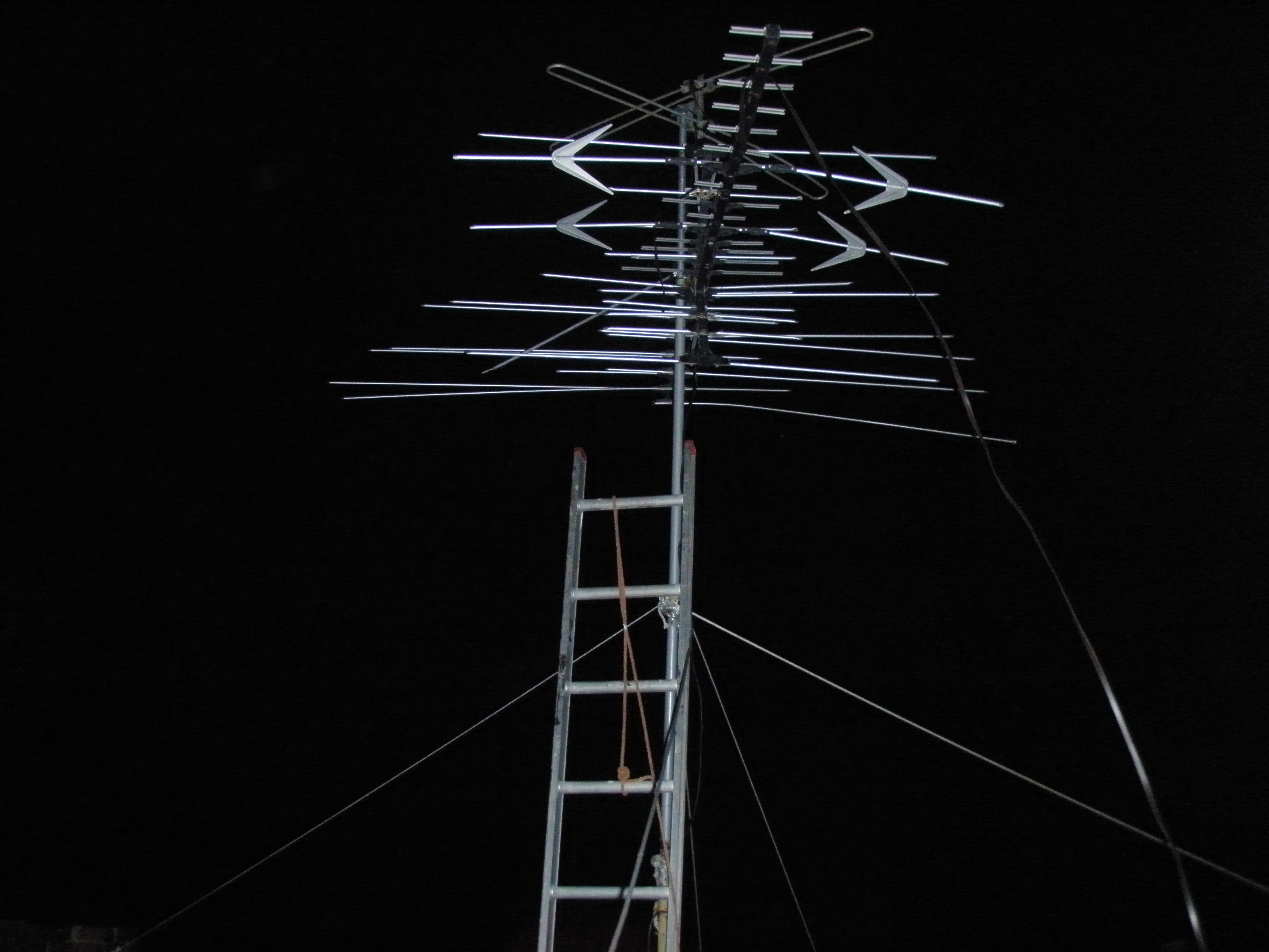
 A UHF television antenna
 An antenna pole setup in a chimney, reaching 35 feet (10.7 meters) off the ground
Small multi-directional: The smallest of all outdoor television antennas. They are designed to receive equal amounts of signal from all directions. These generally receive signals up to a maximum of thirty miles away from the transmitting station, greatly depending on the type. But, things such as large buildings or thick woods may greatly affect signal. They come in many different styles, ranging from small dishes to small metal bars, some can even mount on existing satellite dishes.
Medium multi-directional: A step up from the small multi-directional, these also receive signals from all directions. These usually require an amplifier in situations when long cable lengths are between the television receiver and the antenna. Styles are generally similar to small multi-directionals, but slightly larger.
Large multi-directional: These are the largest of all multi-directional outdoor television antennas. Styles include large "nets" or dishes, but can also greatly vary. Depending on the type, signal reception usually ranges from 30 to up to 70 miles.
Small directional: The smallest of all directional antennas, these antennas are multi-element antennas, typically placed on rooftops. This style of antenna receives signals generally equal to that of large multi-directionals. One advantage that small directionals hold, however, is that they can significantly reduce "ghosting" effects of television picture.
Medium directional: These antennas are the ones most often seen on suburban rooftops. Usually consisting of many elements, and slightly larger than the small directionals, these antennas are ideal for receiving television signals in suburban areas. Signal usually ranges from 30 to 60 miles away from the broadcasting station.
Large directional: The largest of all common outdoor television antennas, these antennas are designed to receive the weakest available stations in an area. Larger than the medium directional, this type of antenna consists of many elements and is usually used in rural areas, where reception is difficult. When used in conjunction with an amplifier, these antennas can usually pick up stations from 60 up to and over 100 miles, depending on the type.
The use of outdoor antennas with an amplifier can improve signal on low signal strength channels. If the signal quality is low repositioning the antenna onto a high mast will improve signal
Installation
 A short antenna pole next to a house.
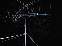
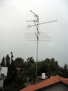 Multiple Yagi TV aerials in IsraelSee also: Radio masts and towers
Antennas are commonly placed on rooftops, and sometimes in attics. Placing an antenna indoors significantly attenuates the signal available to it. [7] [8] Directional antennas must be pointed at the transmitter they are receiving; in most cases great accuracy is not needed. In a given region it is sometimes arranged that all television transmitters are located in roughly the same direction and use frequencies space closely enough that a single antenna suffices for all. A single transmitter location may transmit signals for several channels.[9]
Analog television signals are susceptible to ghosting in the image, multiple closely spaced images giving the impression of blurred and repeated images of edges in the picture. This was due to the signal being reflected from nearby objects (buildings, tree, mountains); several copies of the signal, of different strengths and subject to different delays, are picked up. This was different for different transmissions. Careful positioning of the antenna could produce a compromise position which minimized the ghosts on different channels. Ghosting is also possible if multiple antennas connected to the same receiver pick up the same station, especially if the lengths of the cables connecting them to the splitter/merger were different lengths or the antennas were too close together.[10] Analog television is being replaced by digital, which is not subject to ghosting.
Rooftop and other outdoor antennas
Aerials are attached to roofs in various ways, usually on a pole to elevate it above the roof. This is generally sufficient in most areas. In some places; however, such as a deep valley or near taller structures, the antenna may need to be placed significantly higher, using a lattice tower or mast. The wire connecting the antenna to indoors is referred to as the downlead or drop, and the longer the downlead is, the greater the signal degradation in the wire.
The higher the antenna is placed, the better it will perform. An antenna of higher gain will be able to receive weaker signals from its preferred direction. Intervening buildings, topographical features (mountains), and dense forest will weaken the signal; in many cases the signal will be reflected such that a usable signal is still available. There are physical dangers inherent to high or complex antennas, such as the structure falling or being destroyed by the weather. There are also varying local ordinances which restrict and limit such things as the height of a structure without obtaining permits. For example, in the USA, the Telecommunications Act of 1996 allows any homeowner to install "An antenna that is designed to receive local television broadcast signals", but that "masts higher than 12 feet above the roof-line may be subject to local permitting requirements." [11]
Indoor antennas
As discussed previously, antennas may be placed indoors where signals are strong enough to overcome antenna shortcomings. The antenna is simply plugged into the television receiver and placed conveniently, often on the top of the receiver ("set-top"). Sometimes the position needs to be experimented with to get the best picture. Indoor antennas can also benefit from RF amplification, commonly called a TV booster. Indoor antennas will never be an option in weak signal areas.
Attic installation
Sometimes it is desired not to put an antenna on the roof; in these cases, antennas designed for outdoor use are often mounted in the attic or loft, although antennas designed for attic use are also available. Putting an antenna indoors significantly decreases its performance due to lower elevation above ground level and intervening walls; however, in strong signal areas reception may be satisfactory.[12] One layer of asphalt shingles, roof felt, and a plywood roof deck is considered to attenuate the signal to about half.[13]
Multiple antennas, rotators
 Two aerials setup on a roof. Spaced horizontally and vertically
It is sometimes desired to receive signals from transmitters which are not in the same direction. This can be achieved, for one station at a time, by using a rotator operated by an electric motor to turn the antenna as desired. Alternatively, two or more antennas, each pointing at a desired transmitter and coupled by appropriate circuitry, can be used. To prevent the antennas interfering with each other, the vertical spacing between the booms must be at least half the wavelength of the lowest frequency to be received (Distance=λ/2).[14] The wavelength of 54 MHz (Channel 2) is 5.5 meters (λ x f = c) so the antennas must be a minimum of 2.25 meters, or ~89 inches apart. It is also important that the cables connecting the antennas to the signal splitter/merger be exactly the same length, to prevent phasing issues, which cause ghosting with analog reception. That is, the antennas might both pick up the same station; the signal from the one with the shorter cable will reach the receiver slightly sooner, supplying the receiver with two pictures slightly offset. There may be phasing issues even with the same length of down-lead cable. Bandpass filters or "signal traps" may help to reduce this problem.
For side-by-side placement of multiple antennas, as is common in a space of limited height such as an attic, they should be separated by at least one full wavelength of the lowest frequency to be received at their closest point.
Often when multiple antennas are used, one is for a range of co-located stations and the other is for a single transmitter in a different direction.
Safety
- TV antennas are good conductors of electricity and attract lightning, acting as a lightning rod. The use of a lightning arrestor is usual to protect against this. A large grounding rod connected to both the antenna and the mast or pole is required.[15]
- Properly installed masts, especially tall ones, are guyed with galvanized cable; no insulators are needed. They are designed to withstand worst-case weather conditions in the area, and positioned so that they do not interfere with power lines if they fall.
- There is inherent danger in being on the rooftop of a house, required for installing or adjusting a television antenna.
See also
References
- ^ http://www.dennysantennaservice.com/1496626.html
- ^ BBC: Digital switch advice 'shocking' 9 of 14 installers gave bad or misleading advice, suggesting that people are likely to need a new aerial for digital switchover ... 5 told the mystery shopper they would need a "digital aerial", when in fact there is no such thing.
- ^ http://www.kyes.com/antenna/rabbitear.html
- ^ http://www.electronics-tutorials.com/antennas/antenna-basics.htm
- ^ http://www.terrestrial-digital.com/faqs.html#faq5
- ^ UK aerial groups In the UK transmitters are grouped into A, B, C, D, E, and K frequency bands and located so that, as far as possible, they are all in the same direction for receivers in a given region. This allows optimal reception of all stations by a single fixed narrow-band (and hence high-gain) antenna pointing in a fixed direction.
- ^ http://www.robsaerials.com.au/What_you_Need.php
- ^ http://www.tvantenna.com/support/tutorials/atticantennas.html
- ^ UK TV transmitters
- ^ http://www.tvantenna.com/support/tutorials/combining.html
- ^ http://www.fcc.gov/mb/facts/otard.html
- ^ http://www.tvantenna.com/support/tutorials/atticantennas.html
- ^ http://www.terrestrial-digital.com/faqs.html#faq9
- ^ http://www.tvantenna.com/support/tutorials/combining.html
- ^ http://www.nojolt.com/lightning_protection_for_tv_antennas.shtml
External links
- Article on the basic theory of TV aerials and their use
- Consumer Electronics Association antenna mapping page
- http://www.siber-sonic.com/FM_reception/rooftop.html
- NEC Lab - A tool to design and test television antennas.
Categories:- Antennas (radio)
- Radio electronics
- Radio frequency antenna types
- Radio frequency propagation
- Radio technology
- Television terminology


Wikimedia Foundation. 2010.